I generally run an 18 psi primary and a 12psi secondary for 30 psi
total. However the pressure never gets that high as the air
spring
accepts all the coolant expansion without reaching 30 psi.
Dave Leonard
I don't see how you figure they are in series Dave.
When the first cap goes off the pressure in the second chamber
will become 33.5 psi absolute immediately which will over power
the 12 pound spring in the second cap. These caps operate
on spring pressure. Here is a diagram.
BTW do you have a 3 to 4 inch micrometer for measuring the rotor
housings?
Paul Lamar ...No rotor no motor.
------------------
Paul, I don't agree with your analysis of the radiator caps
operation. Let's
take one cap, venting to atmosphere, The pressure in the system has
to rise
enough to overcome the spring + the outside pressure of the
atmosphere. So,
with a 10# cap, the pressure must raise to 25 psi (absolute) when
you are at
sea level. As you go up in altitude, the *absolute* pressure will
drop as
the atmospheric pressure drops.
Now, lets install a chamber with another (15# ) pressure cap. When
the first
cap starts to relieve, it pressurizes the other chamber, and the back
pressure on the first cap rises. So the *absolute* pressure in the
engine
is = pressure in second chamber + pressure relief of first chamber.
If
sufficient pressure is transferred into the second chamber, then the
*absolute* pressure in the engine is = atmospheric + pressure relief
value
of second cap + pressure relief value of first cap.
All of this assumes that the flat rubber seal on the cap (that is
loaded by
a flat disk spring) can withstand the cap pressures.
Bill Schertz
KIS Cruiser # 4045
Yes that is precisely the problem. I will build a test rig in a few
days
and see how much pressure it will hold. These seals are not designed
for significant pressure.
Here is what the test rig should look like.
--
Paul Lamar ...No rotor no motor.
--------------------------------------------
Took me all after noon to make this aux pressure
tank including two trips to the hardware store.. I made it
out of 1 1/2 " pipe parts and two tubeless tire schrader
valves. Holds pressure fine. One must pressure test
all the parts to make sure none leak or the test of
the cap is inconclusive.
I have two caps to test. A 16 psi by CST
and a 30 psi by C&R racing. I suspect they will all be
different as there is no specification for holding pressure
above the pressure release valve. Nor are they expected
to hold significant pressure in that area.
I'll hook everything up in a few hours and gets some
results.
--
Paul Lamar ...No rotor no motor.
Paul, I suspect that you are right about the pressure relief area of the
cap. There seems to be quite a difference between caps in that area.
In other words, some caps I used seemed to leak there, but most did
not. In order to be more sure about it, I rigged it closed by flowing
JB weld up around the top.
Otherwise, the pressures are in series because the pressure in the
second can is not pressing down on the "diaphragm" in the the first cap,
and adding to its opening pressure.
Yes, I do have a large micrometer for measuring the rotor housings.
Maybe this weekend if I run out of honey do's.
--
Dave Leonard
Turbo Rotary RV-6 N4VY
http://members.aol.com/_ht_a/rotaryroster/index.html
http://members.aol.com/_ht_a/vp4skydoc/index.html
----------------------------------------
Well after the better part of two days and a dozen trips to the
hardware and auto parts store (Stay away from Autozone.
They sell junk. More on that later.) The jury is still out
on whether this will work or not.
I had to scrap the 1 1/2 inch cast iron pipe based aux tank as I could
never get the pipe threads to stop leaking no matter how many
layers of Teflon tape I put on there and over a 100 foot pounds of torque
with a big pipe wrench. The Chinese cast iron pipe parts may have had
something to do with it but that is all the hardware store sold.
I had to start over on the aux tank. I made a PVC aux tank in a
half hour and it worked fine.
I never had any trouble with the half dozen tubeless tire
schrader valves except the ones I got from Autozone were impossible
to install in the .625 hole size they specified.
I torque off a small hose clamp screw and sure enough it was made
in Taiwan. Autozone again. That was a bear to get off. I had to
grind it off on the grinder. Fortunately there was enough room
around it to do that. I found some made in the USA in
Kragen.
Well I got the main tank to stop leaking after coating the
1/4 pipe plugs with Teflon tape and torquing them down
hard. Pipe threads suck. O ring fittings are better.
A tub full of water is invaluable when tracking down leaks.
Then ready for test!!!! Pumped the complete system up to 30 psi
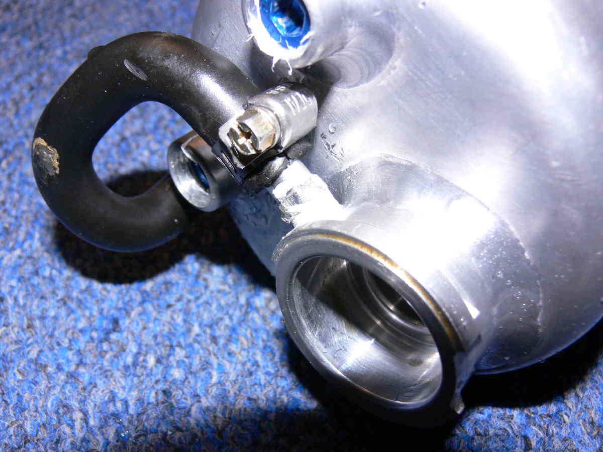
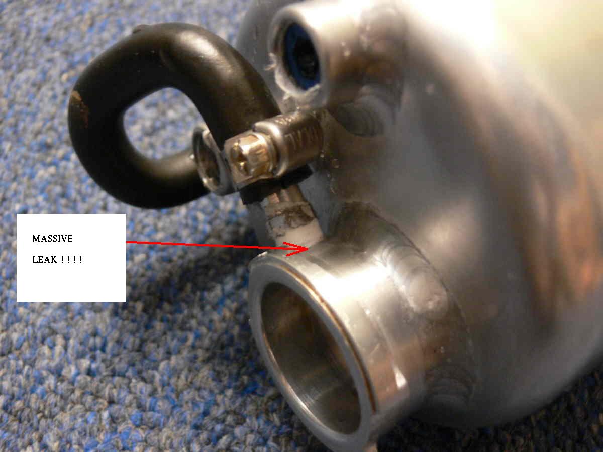
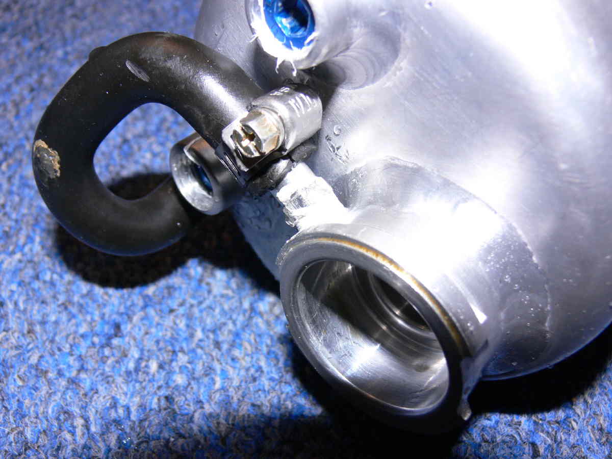
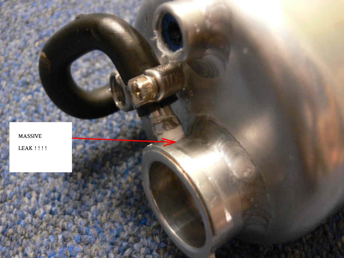
and the main tank held pressure but the 1/4 inch hose joint between
the pressure cap and the aux tank leaked like a sieve.
Ed Klepeis made this tank for me and the 1/4 hose overflow was
pipe threaded and screwed into the pressure cap neck. Not Ed's fault
as these parts are not expected to take 30 psi. They just pass the
over flow to the coolant recovery tank. On the other hand if they
leak air the coolant won't flow back into the system from the overflow
tank. In that case Ed I am thinking of shipping it back to you so
you can welded it up.
What say you Ed?
This is turning into a month project and untold amounts of money and time
:)
My advice guys is forget it and just use one 30 psi pressure cap.
BTW if you are not pressurizing your system with a pre flight test
while watching a pressure gage for leak down you have no idea
if your cooling system is working or not working and not leaking.
Paul Lamar ...No rotor no motor.
Paul;
This all seems to be a bit of a tempest in a teapot (or overflow pot), and
a
repeat of what has already been shown.
I have the same setup on my airplane; 23-24# cap on filler neck, 13# cap
on
the overflow bottle. I also have a Schrader valve to pressurize the
system.
I have done this, and the pressure goes up to close to 40 psig. before
pressure relieves from the overflow bottle.
The 24# cap is a Moroso and does not leak when the overflow bottle is
pressurized. The 13# cap is a cheapy (probably from Autozone :) ). It
could be that a cheapy primary cap would leak at upper seal with the
pressure on the relief side.
If one were to fill the system and the overflow bottle; coolant would vent
overboard on the initial heatup. Air would be drawn back in on cooldown,
and be compressed on subsequent heatup.
When running the engine I find that the pressure gets up to 23# relatively
quickly, and then slowly continues up as the air in the overflow bottle is
compressed. The pressure drops quickly with some cooldown to the pressure
in the overflow bottle (as expected, just a bit of contraction in the
system
drops the pressure across the primary cap to zero).
That's the point of having the two caps. Otherwise a decrease in engine
power (and concomitant slight drop in coolant (and engine temp) results in
zero system gauge pressure.
This is necessarily a problem, but if you level of at cruise with high
engine rpm; you might like some pressure in there.
Al
----------------------------------------------------------
All this maybe true Al but why do it that way? Assuming for the moment it
works I see no advantage over the RX8 one pressure can way of doing it.
I see at least one disadvantage and that is there are more areas for
potential leaks to develop. Two caps to fail instead of one.
You need at least two pressure gages. One on the main system and one
on the hose between pressure caps to monitor the function of
the series system.
The other thing is it does not address the air and steam separation
function like the RX8 system does.
If you want more then 30 psi you could use an industrial pressure
relief valve set to anything and a sealed filler cap.
The rad integrity is soon going to come into question because nobody
is using over 30 psi in their rads except us. The rad is getting
pressurized
and de pressurized every time you fly. Much like an airliner fuselage.
Thin wall aluminum tubing brazed to aluminum header tanks are probably
not renowned for their fatigue characteristics :)
Paul Lamar ...No rotor no motor.
Dear Paul
Send the tank back to me I''ll see if I can fit and weld say 1/8''
npt bung on the side of the filler neck. I have been following the talk on
this two cap system and don't understand it.What every happened to keeping
it simple what do they hope to gain with it. correct me if Im wrong. I have
alot of one cap systems flying out there with no problems is there something
i'm missing.
Regards
Ed Klepeis
If you can weld that 1/4 inch pipe 360 degrees you are a mirical worker Ed.
You must have a tig torch the size of a tooth pick :)
I was thinking of trying JB Weld.
Paul Lamar ...No rotor no motor.
The Rotary Engine NewsLetter. Powered by Linux.
ACRE NL web site.
http://www.rotaryeng.net
Copyright 1998-2005 All world wide rights reserved.