Will trade a whole CD full of cad files for an FEA on this 30 mm wide
steel ring.
The 40 mm dia. steel rollers exert a force of 2000 pounds or 900 Kg
radially outward. I also would like the contact stresses as well if
possible.
The Rockwell hardness is C64.
--------------------------------------------
I am homing in on a cheap 120,000 RPM turbo compound gear box. Mostly off
the shelf parts.
Paul Lamar ...No rotor no motor.
----------------------------------------------
Paul,
I loaded 4340 from my standard library. This is 4340 normalized and not
hardened all the way to it's max hardness.
The red areas are questionable only in that I assumed a "nip" between the
plant gears and the ring gear as 1mm. If I used an infinitely sharp nip
you'd slice right through the material no mater how strong it is and that's
not realistic.
I don't have a lot of time on this (15min) so there is no tuning.
I did discover that if you do a study without an external constraint of some
kind the part zips off into space because the software iterates through the
nodes and even the least amount of force difference 10^-13 in this case
causes the ring gear to drive out of sight. Interesting to watch!
So, I put a constraint opposite one of the contact points to keep the ring
gear from flying off.
-Ben
Thanks Ben! Wonderful!!!! We are on the verge of a major breakthrough in
fuel consumption of the turbo compound rotary amounting to 15% to 20%
better. One false start with the Rotrex gear box I am afraid.
------------------------------------------
If I am doing the conversion right N/m^2 5.979 + 008 is 86,000 psi.
Does that sound about right?
Paul Lamar ...No rotor no motor.
Hi Paul,
That's correct. Since, you're heat treating it up to 100ksi you can slide
the stress scale down proportionally. The 86Ksi comes out of the library.
I didn't bother to edit it.
86ksi is not bad for something like gears. There is a tradeoff between
toughness and strength, they are not synonymous. You alloy up but there are
all kind of issues with trying to go with stronger material at the expense
of machinability. That's why PSRU tend to grow in size with increasing
horsepower.
Let me run another study with 100ksi material.
-Ben
Don't bother. I have another one that is more important Ben.
I'll get a dwg on it to you shortly. It is very simple.
BTW what would be the spring rate on that ring. In other words pounds per
inch of deflection.
Paul Lamar ...No rotor no motor.
----------------------------------------------------------
Take the 2,000lb load and divide it by the max displacement.
In this case it was .3829mm. That's equal to .3829mm/25.4mm/in which is
0.001507480314960629921259842519685 (lol) and that equals
1326717.1585270305562810133194045 or 1.3 million pounds per inch. In other
words, this ring is no spring!
Are you getting 2,000lbs from the centrifugal force on a planet gear zipping
around inside that orbit? Is the orbit gear moving, too?
-Ben
--------------------------------------------------------------------
No. What we intend to do is heat the outer ring to about 500 F or so and
drop it down over cold soaked rollers. This will apply a constant pressure
in the line contact area.
Another part of the design is these three 5 mm thick telescopic rings the
outer one of which is 40 mm in dia and 30 mm long. Again loaded with 2000
pounds or 900 Kg. Consider the block a 2000 pound block or 900 Kg made from
4340 with a 100,000 psi yield. Same for the rings.
My question is does this configuration act like a leaf spring and result in
lower stresses in the individual rings than would be the case if it was one
solid ring 15 mm thick 40 mm OD? And what are they? Spring rate?
I'll show the complete design shortly.
Hopefully we will be able to do a FEA on the complete assemble.
Paul Lamar ...No rotor no motor.
-----------------------------------------------
Hi Paul,
That configuration would be studied as a laminate with transverse shear as
zero. I'm afraid this configuration is more prone to distortion than a
solid ring of the same size and weight. You can mitigate the effects of
this by bonding the rings or mechanically connecting them together via
splines or fasteners.
The good news is that this design doesn't have an unconstrained point(s) as
would leaf springs. Therefore, the loads would track around the circle and
meet at the other side. However, it does this 3 independent times and there
is no benefit from shear constraints between members.
The short answer is that this is not a leaf spring and it's not a solid
cylinder. It's somewhere in between.
-Ben
----------------------------------------------------------
I am to infer then it is not possible to determine the stress in the
individual rings taking them all together?
How about if we divided the load assuming each one took one third and doing
them individual. In that case we might want to tailor the thickness so the
outer ring had the thinnest wall and the inner ring the thickest wall? In
the final design they will be pressed together. Perhaps this is a level of
sophistication we don't need to delve into at this point?
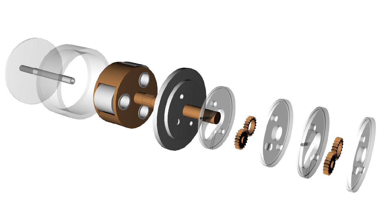
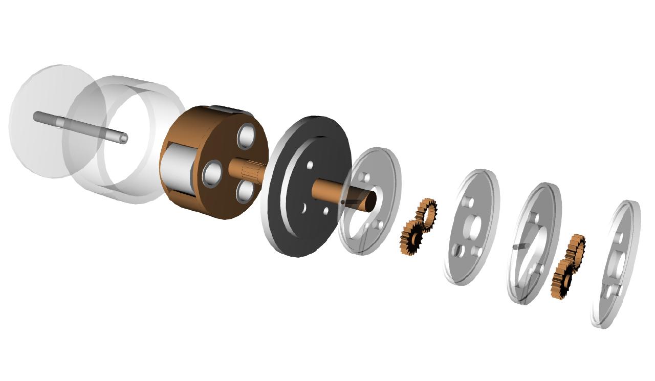
Here are some 3D's of the final friction reduction drive.
It has its own small dry sump oil system to keep the temp rise down. The dry
sump system is of traditional spur gear design.
Cooling fins on the ring might be used to reduce the temp rise.
The considerable centrifugal loads from the rollers and bearings are taken
by the rotating all steel planet carrier.
The bearings are heavy duty off the shelf Torrington rollers with basic load
ratings of 7000 pounds and max speeds of 25,000 RPM.
Input shaft dia is 3/8th OD and output shaft 5/8th OD roughly.
Power transmission goal is 50 HP with 120,000 RPM in and about 12,000 RPM
out. Overall efficiency should be above 95%.
The OD of the unit is about four inches.
The unit is designed to extract excess HP from a turbo charger and return it
to the e-shaft of the rotary thereby significantly increasing the power
without increasing the fuel consumption.
Your basic 1950's turbo compound technology.
Power is taken from the planet carrier with the ring stationary and part of
the housing. Rotating direction of the output shaft is therefore the same as
the input shaft making it compatible with the stock Mazda Turbo II engine.
Paul Lamar ...No rotor no motor.
--------------------------------------------------------------------
Hi Paul,
Now, I see what you are doing. I think you need some compliance from the
outer race. Remember, my discussion of "nip". Years ago I was involved in
the paper industry on a consulting job to determine the amount of nip on
friction drives. What was going on was that (and this is true for all
rollers) the mills were grinding a crown in the rollers to compensate for
the bending of the roller so that there would be a line contact between
rollers. As material technology became better the stiffness of the rollers
reduced the bending and therefore there was too much pressure at the middle
of the roller due to over crowning. Ultimately, we calculated what the
bending of the roller was and reversed that into a crown. Also, we
discovered that the crown isn't really an ogive (circle) nor was it a
parabola as you'd guess but something in between. After all that work we
found that you could put carbon paper between the rollers and get a pretty
good idea of the amount of nip on a roller. Carbon paper is useful for all
kinds of mechanical analysis, but I digress.
With your design you can tailor the nip by either crowning the roller or the
race. Even crowning the back of the race in this case would work if it's
unsupported. Now, I understand your spring-like properties language. You
actually want some springlike properties.
Here's were we have to be careful. Springs work because they take
advantage of the little springs inside their constituent parts, namely the
bonds between atoms. In so doing, they generate heat. Even with a perfect
system of roller to race contact and no slippage you will have lots of
bending albeit very slight and that will generate a lot of heat. I know of
no tool to predict how much heat will be generated by this technique other
than to run it and test it. How about prototyping this with thread spools
and a cut section of an inner tube? How's that for aging me?
Eggenfellner is hinting at a reduction drive that might work something like
what you're doing based on a picture I saw in a magazine this month.
Interesting, for sure.
-Ben
Obviously Ben you are the right man for the job.
That is why we have the oil pump and the scavenge pump
so we can oil cool the beast.
The major breakthrough came when the planetary was combined
with the friction drive drastically simplifying things and doing
away with coil springs. Several of these things are being
developed around the world. Friction drives date back to
the invention of the locomotive on steel rails or probably
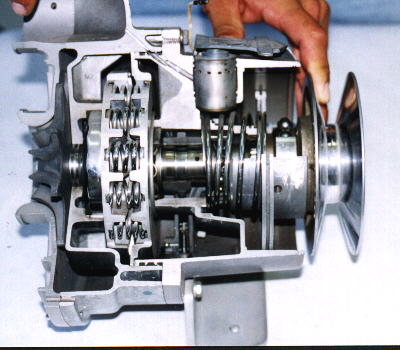
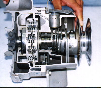
before that. McCullock (Later Paxton) designed a friction
drive super charger in the late 1930's for use in mining
trucks in the Andes. Note all the coil springs in the Paxton.
Here is an exploded view.
Paul Lamar ...No rotor no motor.
The Rotary Engine NewsLetter. Powered by Linux.
ACRE NL web site.
http://www.rotaryeng.net
Copyright 1998-2005 All world wide rights reserved.