snips....
"So theoretically it should be a wash between the engine driven
compressor and the turbocharger since it takes the same amount of energy
to drive the compressor."
As far as net HP output is concerned this is probably true.
Given that this is true, and all the mechanical power to drive the
compressor comes from the core engine, each additional core engine
mechanical HP generated requires 4 HP worth of fuel burned as the core
engine is only 25% or so efficient. On the other hand if all the
power to drive
the compressor is extracted from the waste heat in the exhaust the
overall efficiency will be higher. I think they used the stock
2 speed mechanical driven compressor because it was there in the
original B29 version of the R3350.
Gordon I forgot to explain one thing here. Since the compressor and
the turbine
are on the same shaft, and are geared to the e-shaft on the test
configuration
using the stock turbo charger, in effect it is both a supercharger and a
turbo charger. If the torque from the engine is greater than the torque
from the turbine the compressor will be partly powered by the
engine. This configuration may accelerate the engine RPM faster than the
plain turbo charger. That does not concern us in the aircraft
configuration.
(BTW Due to increased rotational inertia it won't accelerate as fast
as if the engine was powering just the compressor as in a pure
supercharger. On the other hand the engine is sucking out its own
exhaust gas.)
As engine RPM builds up and hopefully excess turbine power rises
more of the torque required by the compressor will come from the turbine
and less from the e-shaft. If there is any turbine torque left over
it will
be applied to to the e-shaft.
Adjustments to this system can be made in several ways.
1)The turbine can be made larger or smaller (A/R changed).
2)The compressor can be made larger or smaller.
3) The gear ratio between turbo charger and e-shaft can be changed.
4) An over running clutch can be added so the engine never drives
the turbocharger.
I suspect that a fixed gear ratio can be found that will work as
is because I suspect the turbine is more powerful than necessary
to merely compress the combustion air at a steady engine RPM.
If this can be made to work the advantage is less heat lost to the
second turbine and its additional hot plumbing required. Not to
mention the simplicity and lighter weight.
Paul Lamar ...No rotor no motor.
Paul,
What you're describing is a single turbine with both the compressor and
the gearbox on the same shaft? Essentially a turbocharger with a gearbox
added and a belt to the engine?
This sounds good, if it can be made to work. In fact this is better than
having the supercharger on its own dedicated belt drive. But how are you
going to add the gearbox to a turbocharger shaft, sandwiched in the
middle?
I certainly think this is better than having two turbines, which I
honestly believe will dump off more exhaust energy than it is worth.
Regards,
Gordon.
Yes exactly.
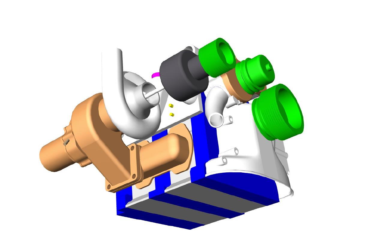
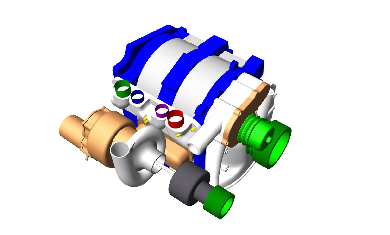
I just finished the 3D. I wanted to make sure everything fits.
I already had to make a change in the diameter of the drive pulley
to get the multi V belt drive to clear the water pump pulley and
still have a 2:1 speed reduction. The drive pulley is now 2.5 inches
and the e-shaft pulley is now 5 inches pitch diameter.
Here is the 3D.
Paul Lamar ...No rotor no motor.
Thanks for the drawing, Paul.
Very interesting.
I'm not sure I'm reading the parts correctly. It looks like the pulley
is in front in the green, behind which is the traction drive in black
followed by the compressor? Or is that the turbine wheel?
Regards,
Gordon.
Yes that is it. The turbine is brown. The dimensions are very close
to the stock turbo charger on the 89 to 91 Turbo II engine.
It needs a little more cosmetic work :)
The traction drive is four inches in diameter and about 2.5 inches
long not counting the output shaft snout. Here is a 3D of
the traction drive.
Paul Lamar ...No rotor no motor.
--------------------------------------------------------
Thanks for the drawings, Paul.
What are those little gears in the front of the traction drive?
Also, I'm wondering how your shaft is going to go right through the
front of the compressor through the air intake opening? You would have
to modify the compressor I would think, plus your intake air would not
have a straight shot in.
Why not put the traction drive in the middle, between the turbine wheel
and the compressor?
Regards,
Gordon.
That is a miniature dry sump cooling system. Traction drive generates
a lot of heat due to flexing of the outer ring. Also traction fluid
is required to cool them and lube them. There is no real metal to metal
contact. Traction fluid actually gets between the parts.
The test unit won't have this. We will use an electric pump
to serve that purpose.
Simple trick is to make a coupling that replaces the nut that holds
the compressor wheel on the shaft. No problem on the straight
shot in. No way to get that on an airplane anyway as the
turbo charger intake is facing the firewall.
The traction drive reduces the RPM of the turbine about 10:1
If we put it between the turbine and the compressor the compressor
would have to get much much larger. Also the heat from the turbine
section would add to the heat problems of the traction drive.
On the stock turbo one of the neat things about it is water cooling.
Placing the traction drive there would preclude the water cooling.
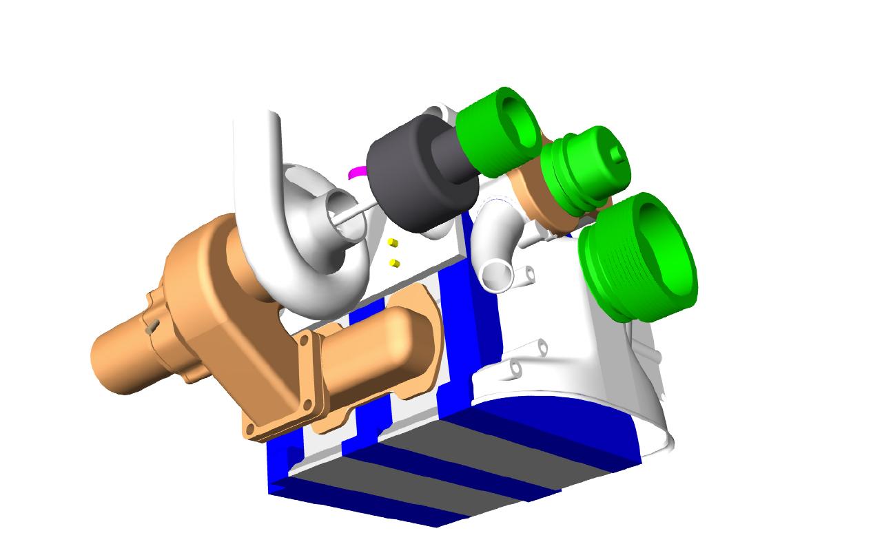
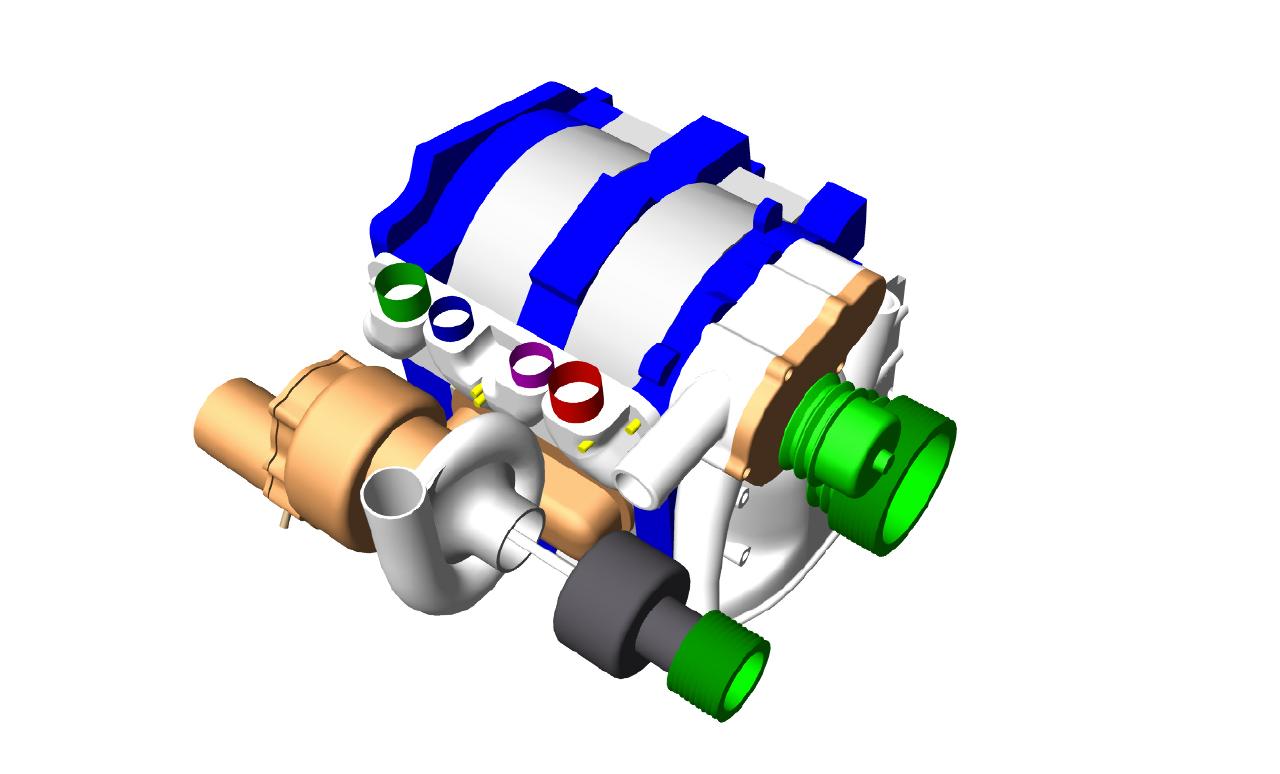
Here is the latest 3D on the system. These things are never done :)
Paul Lamar ...No rotor no motor.
The Rotary Engine NewsLetter. Powered by Linux.
ACRE NL web site.
http://www.rotaryeng.net
Copyright 1998-2006 All world wide rights reserved.