I did a major update to the web site reflecting the
recent break through in the efficiency of the internal combustion
engine.
Paul Lamar ...No rotor no motor.
Paul,
That's a very nice compendium of info on turbo compounding.
Just looking again at your most recent drawing of the proposed layout
using your new-design gearbox, I have to wonder again why you don't put
the box in the middle between the turbine and the compressor.
The sun shaft of the gearbox can be the common shaft on which the
turbine and compressor ride -- and it can pass right through that big
hollow tube on the planet carrier (on which the pulley sits.)
Then you can turn the whole thing right around so your intake mouth on
the compressor is facing into the air stream and the exhaust from the
turbine is facing aft.
Regards,
Gordon.
I think I see what you are up to. Interesting idea.
Keep in mind the sun shaft must be no larger
than 3/8 th while a typical turbo charger shaft can be as large as 1/2"
or 5/8th of an inch. There are whirl mode considerations as you have two
small flywheels separated by a small shaft of finite length. The
dynamics of turbo chargers is more complicated then it looks. Then
you have things like the torsional resonant frequency of the thin
3/8 shaft
with small flywheels on each end. Another issue is heat transfer
from the
turbine to the gear box. It could be made to work with enough R&D but
I suspect the current set up with the shaft coming out of the air intake
to the compressor will be easier to get to work and the lessor evil. For
example it would be easy to introduce a low temp rubber coupling between
compressor and gear box if found necessary. Aerodynamically there is
little or no drawback as the compressor is an annular
intake device anyway. In other words air is taken in in a hollow
cylindrical shape.
The last advantage is this box can be attached to any stock off the
shelf
turbo charger so R&D is simplified.
Paul Lamar ...No rotor no motor.
Paul,
Yes there are some technical and fabrication challenges with this
layout, no question. It is certainly simpler to just bolt the gearbox to
the compressor end of an intact turbocharger unit as you are proposing.
However, it might be worth the extra trouble. Doug has calculated that
ram air effect at cruise could be worth 2 psi of boost. This is four
inches of mercury. If you are cruising at 18,000 feet with an ambient
pressure of 15 inches, you now have 19 inches with just the ram air
boost. This equals about 65 percent power!
If you want to cruise at 75 percent you would only need to add three or
four inches from the supercharger. The less your supercharger works the
more net power you can put back into the engine from the recovery
turbine.
You are also getting a little thrust from the exhaust pipe pointing
straight back too.
Another benefit from separating the compressor and the turbine is that
you will cut down on radiation heat from the turbine to the compressor,
helping to keep your charge cool.
You will get some conduction heat transfer through the shaft from the
turbine into the gearbox, but perhaps a water-cooled turbine would help
there.
As for the size of the shaft and the twisting potential, I agree that's
a thorny issue. Too bad you can't make the shaft a little thicker, but
then you would have to make the rollers bigger diameter to keep the same
ratio, increasing the moment and centrifugal forces, etc.
But if you make the shaft as short as possible, it may be possible to
end up with a workable stiffness.
Regards,
Gordon.
For my purposes ram air won't work as we will be testing it on a dyno.
This sort of development could be down the road. I don't have unlimited
resources so I have to do what I think I can do. I hope to show
some advantage on the dyno and then write an AIAA or SAE paper on the
results. Here is the roller drawing I just completed. From this
you can get a sense of the extreme simplicity of the traction drive.
If the automotive world has half a brain everybody and his brother
should
jump on this and develop it. Boat engines and gen sets are an obvious
immediate application besides light aircraft. If Mazda has half brain
they should jump on it as they have a leg up on the rest of the world
due to 2 million rotary engines sold so far.
Paul Lamar ...No rotor no motor.
Thanks for the drawing, Paul.
Come to think of it, I have to wonder why Mazda has not explored
turbo compounding for the rotary. Like you said, this engine is a perfect
gas generator for spinning a turbine.
I would think though that in auto applications at the low power that is
typical of highway cruise, there is not that much exhaust energy. It
would have to be a pretty small turbine, but then you would run the risk
of over speeding it in full-throttle acceleration.
Regards,
Gordon.
I just think it never occurred to them. I 60 years of reading about engines
on all levels I have never seen anyone publish the dumping losses on exhaust
valves until now. In WW II they did some great work on engines. They obviously
looked at things nobody else ever looked at and have not looked at since.
Naw you just use a computer controlled waste gate in an automotive
application. Here is a 3D showing that.
http://www.rotaryeng.net/RX8.html
With computer control you can do almost anything.
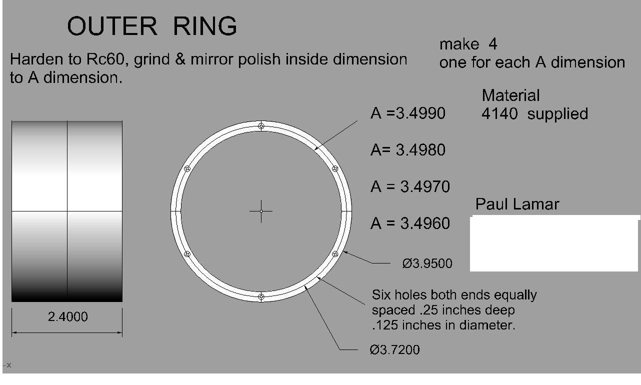
Here is the outer ring design. Weighs 1.88 pounds. We are making four
of differing ID's with a .001 inch increment. There is a trade off
between life and HP capability. The smaller the ID the higher the HP but
the lower the life with a given OD. We will start with the largest and
see at what static torque it slips. Also this design exploits the flexibility
potential of the roller which reduces the stress on the outer ring
while transferring some of the potential for fatigue to the roller.
The small holes have roll pins which fit into slightly over size holes
in the case end covers. This allows the ring to flex while holding it
stationary more or less.
Paul Lamar ...No rotor no motor.
The Rotary Engine NewsLetter. Powered by Linux.
ACRE NL web site.
http://www.rotaryeng.net
Copyright 1998-2006 All world wide rights reserved.