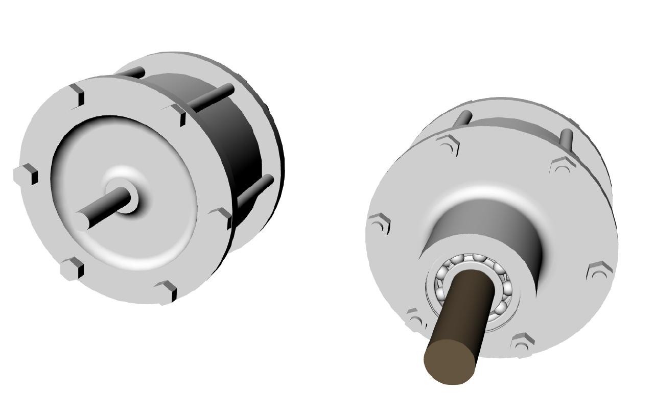
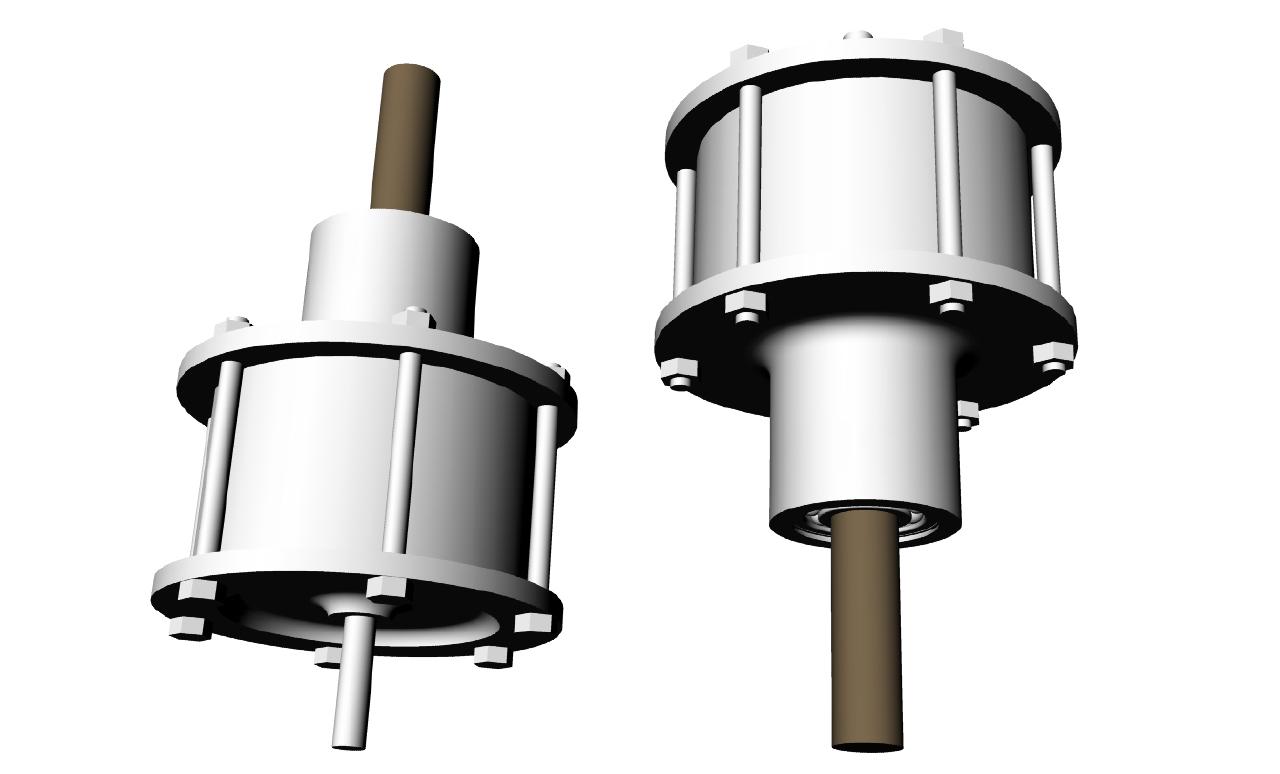
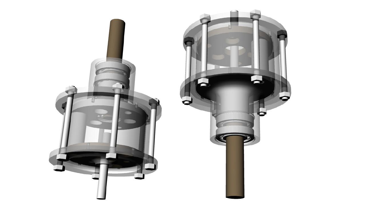
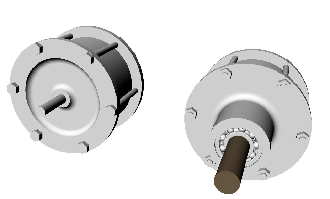
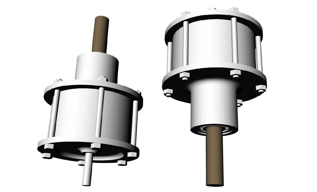
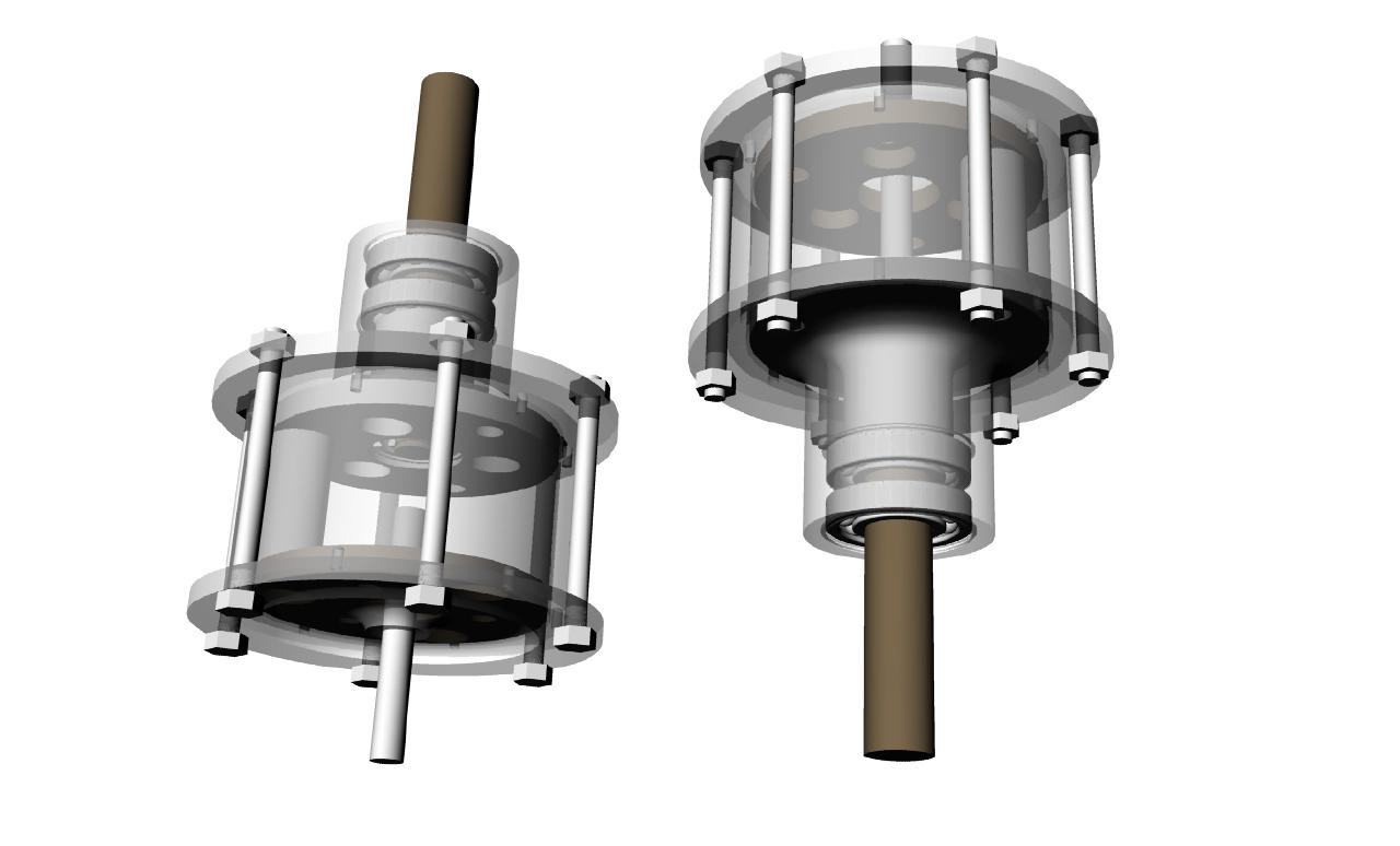
This is what it will look like more or less. Slightly under five
inches in diameter and 7.5 inches long over all.
The flange is about in line with the water pump front surface for
and adapter bracket off some water pump studs or bolts. This will
be the main mounting method.
If this works as well as I think it will work it will drop
the rotary BSFC from .47 to .375 at about 14,000 feet. Better
than most diesels. Not bad for an additional ten pounds over
the turbo model.
-------------------------------------------
I had to shorten it to fit. There is only six inches between
the intake of the turbo charger and the front of the e-shaft pulley.
I may have to machine some off the intake tube on the compressor.
I could probably get another inch of clearance between the back of the
traction box and the turbo charger air intake area by that trick.
The 3/8th input shaft is now only about 2 or 3 inches long.
Consequently the spacing on the traction box output shaft bearings is
less than ideal but it will work for the prototype. The side load or
tension on the belt is only about 105 pounds with 50 HP out at
10,000 RPM shaft output speed.
HP = RPM x Torque / 5252
HP x 5252 / RPM = Torque
Torque = 26 foot pounds or 315 inch pounds.
Side load is therefore 105 pounds on a three inch pulley diameter.
Output shaft bearings are rated at 1700 pounds so it should be OK.
Unfortunately the off the shelf multi V belt pulley is not recessed.
A longer traction box snout could be designed with an off set pulley
like the Mazda water pump pulley allowing more bearing spread.
Some of the guts are missing from the planet carrier to show more
details in this 3D.
Paul Lamar ...No rotor no motor.
The Rotary Engine NewsLetter. Powered by Linux.
ACRE NL web site.
http://www.rotaryeng.net
Copyright 1998-2006 All world wide rights reserved.