>
>> This is what it will look like more or less.
>>
>> The flange is about in line with the water pump front surface for
>> and adapter bracket off some water pump studs or bolts. This will
>> be the main mounting method.
>>
>> If this works as well as I think it will work it will drop
>> the rotary BSFC from .47 to .375 at about 14,000 feet. Better
>> than most diesels. Not bad for an additional ten pounds over
>> the turbo model.
>>
>> -------------------------------------------
>>
>> I had to shorten it to fit. There is only six inches between
>> the intake of the turbo charger and the front of the e-shaft pulley.
>> I may have to machine some off the intake tube on the compressor.
>> I could probably get another inch of clearance between the back
of the
>> traction box and the turbo charger air intake area by that trick.
>> The 3/8th input shaft is now only about 2 or 3 inches long.
>>
>> Consequently the spacing on the traction box output shaft
bearings is
>> less than ideal but it will work for the prototype. The side load or
>> tension on the belt is only about 105 pounds with 50 HP out at
>> 10,000 RPM shaft output speed.
>>
>> HP = RPM x Torque / 5252
>>
>> HP x 5252 / RPM = Torque
>>
>> Torque = 26 foot pounds or 315 inch pounds.
>>
>> Side load is therefore 105 pounds on a three inch pulley diameter.
>> Output shaft bearings are rated at 1700 pounds so it should be OK.
>>
>> Unfortunately the off the shelf multi V belt pulley is not recessed.
>> A longer traction box snout could be designed with an off set pulley
>> like the Mazda water pump pulley allowing more bearing spread.
>> A project for the future after we get some dyno data with this
setup.
>>
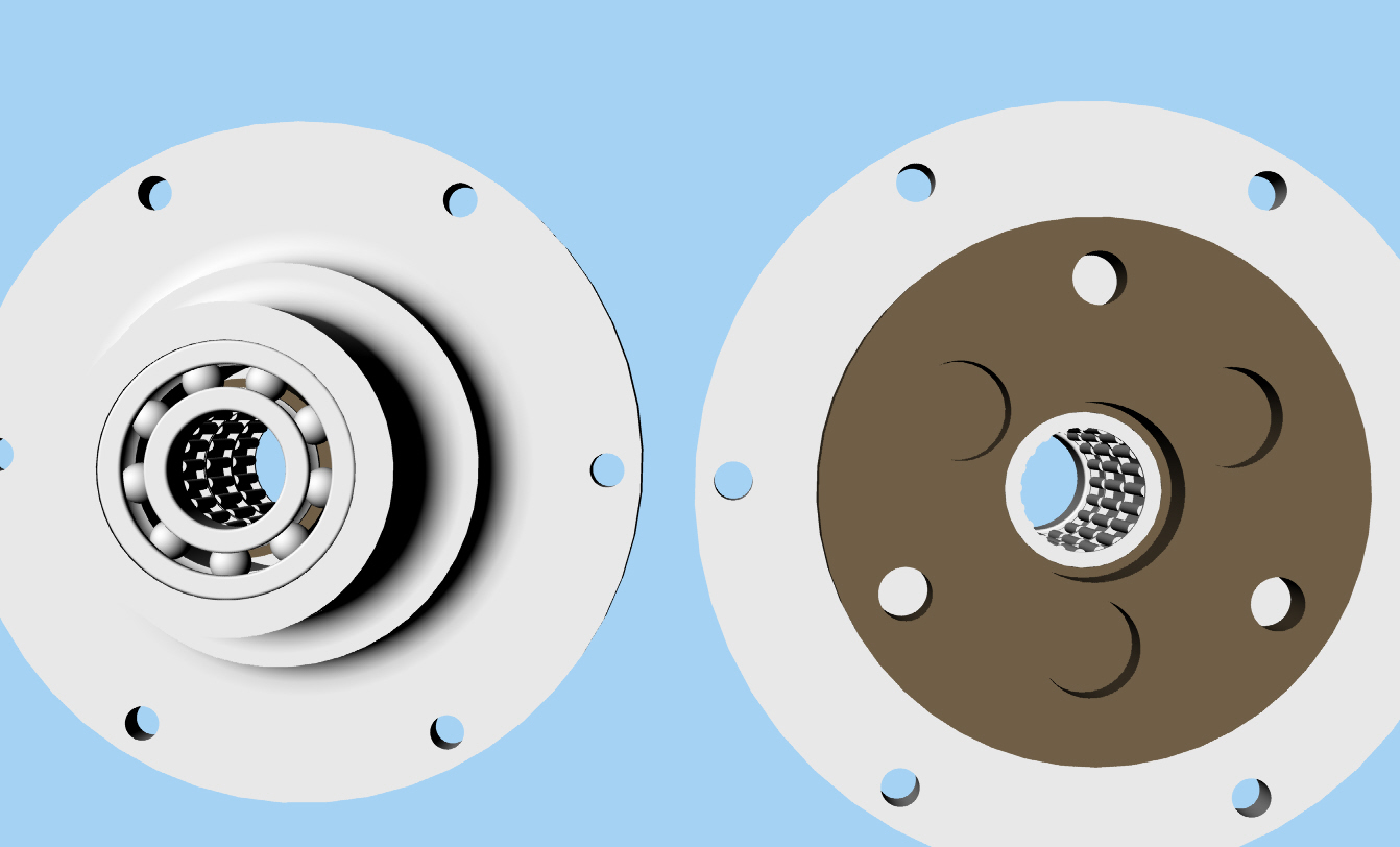
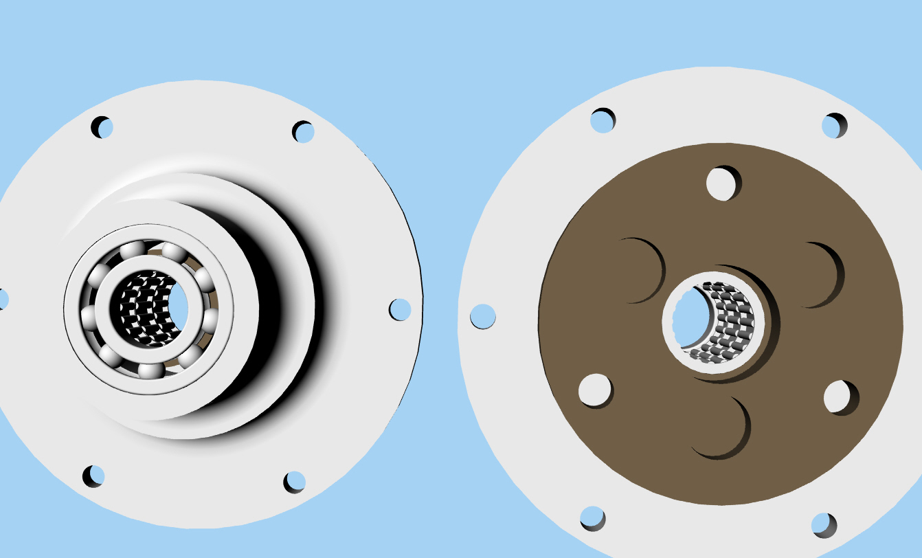
>> Some of the guts are missing from the planet carrier to show more
>> details in this 3D.
>>
>> -------------------------------------------
>>
>> I am slowing coming to understand that ideas are worthless
>> unless you can show that they fit using 3D drawing programs :)
>>
>> Notice the tight space between the drive and the turbo.
>> I know Gordon is going to say I told you so. "You should
>> have put the drive between the turbine and the compressor." :)
>>
>> I still think this can be made to work without the can of worms
>> of putting the traction drive between the turbine and the
compressor.
>>
>> I also still think I can machine the compressor intake down
about one
>> inch
>> and add a bell mouth to enhance air flow into the compressor.
>>
>> You always wanted a turbine engine in your car. Now is the chance.
>> The Mazda Wankel makes an excellent gas generator for a turbine
engine.
>> Paul Lamar
stephen wolpin wrote:
> paul,
>
> nice drawings. rhino is cool.
>
> at 100k rpm, how does the 3/8 input shaft relate to the
compressor shaft
> and how will you assure they are aligned?
>
> i notice the nose piece on the traction box is long while the rear
> bearing area is short; is this necessary? why not move the box toward
> the green drive pulley some? i realize that lengthens the shaft,
yet it
> also allows more room for inlet and rear bearing area.
>
> you could have a fwd cage around pulley for the front bearing so
pulley
> is not cantilevered, if that helps in the side load department.
>
> when do we hear it run?
>
> steve
Short piece of silicone rubber hose? :) Tiny U joint? :)
Lets see 50 HP at 100,000 RPM
HP = Torque x RPM / 5252 Torque is 2.6 foot pounds or 31 inch pounds.
There is a moment on the shaft because the pulley center is off set from
the last bearings Consequently we need a little bearing spread in there
to take moment. The moment is about 50 inch pounds.
These traction drive boxes are basically one big roller bearing so
the input shaft is self aligning. There is no bearing in the back cover.
Just an oil seal. The outer ring is a spring.
http://www.nastecinc.com/traction.htm
http://www.rotrex.eu.com/
It will be after Sun n Fun before we can get it on the dyno at Mazdatrix
as I have to be there for a forum on the subject.
http://www.mazdatrix.com/
Paul Lamar ...No rotor no motor.
Paul,
Nice work on the latest drawings.
No, I'm not going to bug you anymore about where to mount the box. I
think you've got enough on your plate for now.
Anyway, it's a very nice setup and I'm keeping my fingers crossed that
it works as planned.
Regards,
Gordon.
PS: Thanks for that CD, it arrived today and I'm just about to crack it
open.
Your welcome Gordon. How about writing a turbo compound article for
EAA Sport Aviation or Kitplanes magazine. Your a good writer and
the turbo compound needs more exposure.
Heck why stop there I think the Wall Street Journal would also be interested
due to its economic implications..
Paul Lamar ...No rotor no motor.
BTW I keep refining the design. If I were a corporation I would fire
the engineer (me) and go into production :) I added a couple of bearings
to be absolutely sure nothing moves around in an undesirable fashion.
Those one way clutches are sensitive to any side load.
In this 3D you can see the two one way clutches and one needle bearing as well as
the main bearing that takes the belt load. There are two other ball
bearings in the unit. One goes in the back of the planet carrier plate
shown here.
The Rotary Engine NewsLetter. Powered by Linux.
ACRE NL web site.
http://www.rotaryeng.net
Copyright 1998-2006 All world wide rights reserved.