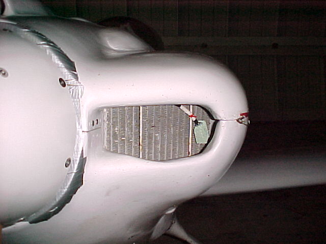
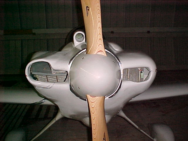
Howdy Paul,
Since most of you guys are flying out faster than I the dimensions may
be different. I would like your input on my rad ducting. I will send a
separate email with pics and dimensions .
Thanks for your time,
Geir
Please note: forwarded message attached
Paul
I found this 4-21-2005 email to be very helpful. I read your "How to
Cool"
report on the website the other day. I few spelling mistakes but
otherwise
good. You might consider putting in this info as well.
I'll go with thin cores 1 1/4 inches for a total of 720 cubic inches.
Perhaps I'll tweak the end tanks a little bit to bring the total
closer to
780. 2"x2" seems very large.
Doug
Paul Lamar said........
This is what I was trying to explain at Sun & Fun.
The 20 percent rule gives an angle that is a function of the length of
the
core
and its area. For cores of constant area but variable width the angle
remains the same.
In our case we have a length of about 24 inches to work with, width of
about
20 inches
and a core frontal area of 20 by 20 inches or so. Angle is therefore
around
12 degrees.
Total cubic inches for oil core and water core is then about 825 cubic
inches
or so. The stock Mazda oil cooler is about 275 cubic inches alone. The
oil
requires one third of the cooling. Rad core volume is therefore 550 cubic
inches.
If the ducting proves effective and is well sealed this rad core volume
number
could drop. Chuck Dunlap and Perry Mick with well sealed rad diffusers
are
getting along well with less than about 500 cubic inch rad cores.
This all means we should be able to use a cooling system opening
height of
four
inches. The top front of the rad can be four inches below the fly wheel.
Some
fire walls will require a flat rad and other deeper fire walls will
allow a
little
down slope to the rad position.
The 20 percent rule is for a climb out speed of about 100 MPH. Higher
climb
speeds
will require less opening area and slower climb speed more opening area.
Racing airplanes can use very little opening area as shallow and short
climbs can be used.
None of this is critical as long as there is enough opening area for the
slowest climb speed (max angle). Excess opening area will hurt little if
cowl flaps
are used. This is because blocking the air going into the cooling system
will
result in a pressure build up well ahead of the opening. This is called
external
diffusion and self streamlines the opening so to speak. A well understood
process
as most airplanes are faster with the cowl flaps nearly closed.
This all depends on the back side of the core being well away from
obstructions
and the inlet diffuser being well sealed of course. All bets are off if
the cowl inner surface is used as part of the ducting as it is very
difficult
to seal the duct with high internal air pressures. Things move around.
Rads
should
also be protected from radiant heat from the exhaust. Two pass rads under
the engine
simplify the plumbing as both coolant inlet and outlet are at the back of
the rad.
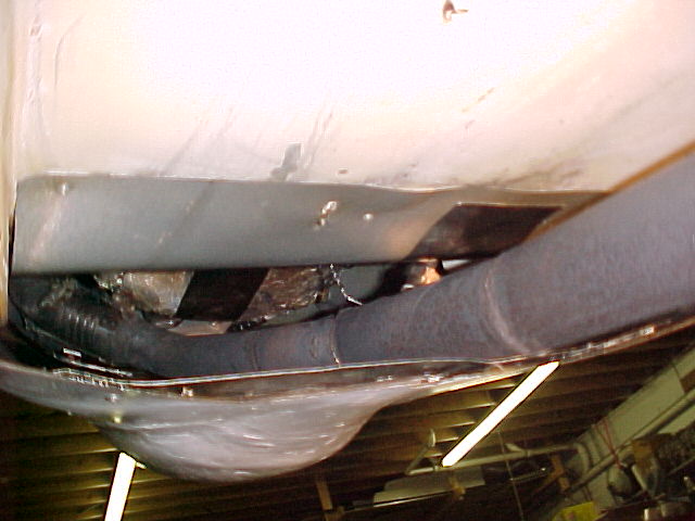
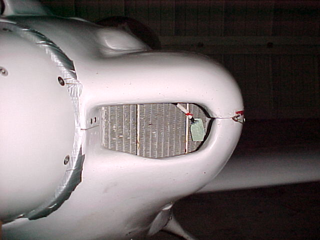
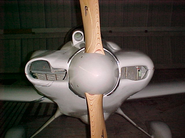
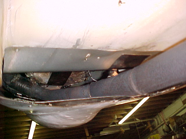
As way of illustrating some of these points here is Tracy Crook's (not
working well)
right side diffusers, scoops and oil and water rads. The last 3D is
the fix.
Paul Lamar
Hi Paul;
Do you know the inlet opening area in^2 feeding each of Tracy's evap
cores and oil cooler?
The exit area out the bottom of the cowl?
Thanks
Cary
Not off hand but I could roughly calculate it.
Based on a 10 inch spinner and scaling them off this pict
I get roughly 28 square inches on the left and 16 square inches on the right
of the pict for a total of 44 square inches.
That should be enough for a 220 square inch total heat exchanger using the 20% rule.
A 220 square inch core 2 inches thick would be 440 cubic inches.
Tracy has two rads about 3.5 inches thick 11" by 10" as I recall
so that is about 770 cubic inches for both and a stock oil cooler.
On the other hand if the spinner is 12 inches the intake area number goes up to
66 square inches or enough for a 330 square inch rad or 660 cubic inches
total oil and water two inches thick.
Tracy has a lot of air leakage around the right opening and no cowl flap.
A cowl flap would improve his cooling greatly. However Tracy does not feel
that climbing out at max angle is necessary. Spoken like man that lives
in flat Florida :) If you climb out at 120 mph instead of 100 mph
The dynamic pressure goes from .18 psi to .26 psi increasing the mass air flow
through the rad.
On his RV8 he will have to use a Kays & London wedge diffuser as his single rad
is vertically mounted on the cool side of the engine so it will be interesting
to see what he winds up with as far as opening area, exit area and cowl flap if any.
The 20% rule of thumb appears to be conservative. Perhaps with a good
cooling system design and construction it could be reduced to 15%.
Better to be safe than sorry. It is always easier to cut things down than
make them bigger.
-----------------------------------
ops it should have been the last picture.
Paul Lamar
The Rotary Engine NewsLetter. Powered by Linux.
ACRE NL web site.
http://www.rotaryeng.net
Copyright 1998-2006 All world wide rights reserved.