snips....
> All I need is something simple to work on the
dyno.
> Turbo charged 2nd gen engine. Ignition is not
> mandatory as
> I can lash something up that will fire both plugs
20
> dgrees
> BTDC. I can go with the CAS or build an RX8 style
> trigger wheel and pickup. I am using stock 2nd gen
> injectors.
>
> I ordered the bare boards from DIY.
>
> Is msnsextra code C or 68HC908 asm source?
>
> BTW I am thinking two of these could be used in an
> airplane
> with a 37 pin plug on the instrument panel. Unplug
> one and
> plug in the other as a preflight backup check.
They
> are cheap.
>
> Paul Lamar ...No rotor no motor.
msnsextra is asm. Latest version, and source, is
available in the zip file found here:
http://megasquirt.sourceforge.net/extra/files/
Stock 2nd gen injectors can be either high or low
impedance depending on year, so you may want to
check
to see what you've got.
Roger.
Thanks for your help Roger.
No problem with the injectors. I can figure it
out. Thats what ohmmeters are for. I spent 20 years
manufacturing electronic test equipment. I have some
injectors I probably need a few more.
BTW where is the s record file for the extra
version?
Also where do I get the assembler. Is Motorola
giving it out for free?
---------------------------------------------
I have been looking over the code and it looks
pretty simple and straight forward.
The extra version source file is four or five times
larger than the early source. I think I will start
with
the 2001 simple version.
Here is the flow chart. Pretty simple.
A simple way to do the ignition is use two RX8 or
3rd gen
mag pickups and a steel plate with one large tooth.
The pickup are oriented 180 degrees apart around
the e-shaft pulley. One pickup fires the front rotor
plugs and the second fires the rear rotor plugs.
The steel plate is slotted to adjust the fixed
timing.
One pickup can also feed the tach signal. No CAS
required.
Paul Lamar ...No rotor no motor.
That should work, but you'll need some way of
conditioning the VR pickup signal, and then sorting
out the coil charge time. A GM 4-pin HEI module will
work for this. Will the rotary start OK at fixed
timing, or is some retard needed during cranking?
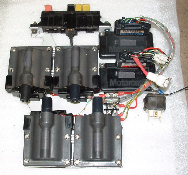
I'm presently running a twin EDIS ignition system on
my rotary. The EDIS4 module (from an early 90's Ford
Escort 1.9) was developed by Ford to address the
cpu-intensive task of toothed wheel decoding. It's a
stand-alone module that will:
1.) Decode a 36-1 wheel/VR sensor combination
2.) Drive two coil outputs each fired every 360
degrees, with 180 deg separation. This works
perfectly for the rotary, as one is front rotor, and
the other rear.
3.) Provide automatic coil charge time and current
limiting.
4.) Offers 'multi-spark' at low rpm (useless for
aviation apps, but a neat idea nonetheless).
The module will run fixed timing with no ecu
connector, or you can connect two wires between the
module and MegaSquirt, and have full control over
ignition timing.
Wiring details here, about 2/3 the way down the page:
http://www.megasquirt.info/ms2/EDIS.htm
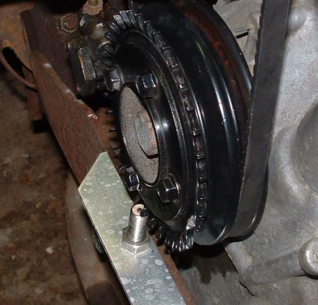
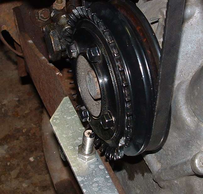
In a previous engine install, I cut 36 teeth into the
outer rim of the e-shaft pulley, ground one tooth
away, and mounted an industrial VR pickup in-line with
the rim. You could do the same in short order if you
have access to a rotary indexing table and a mill.
I've attached a couple pics of that setup.
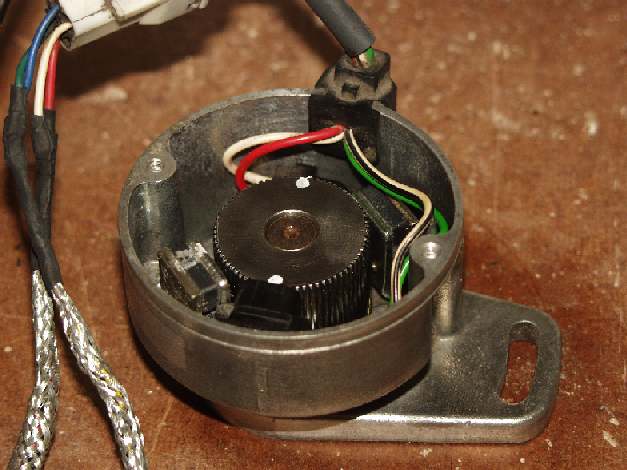
Just to confuse matters even further, I'm now running
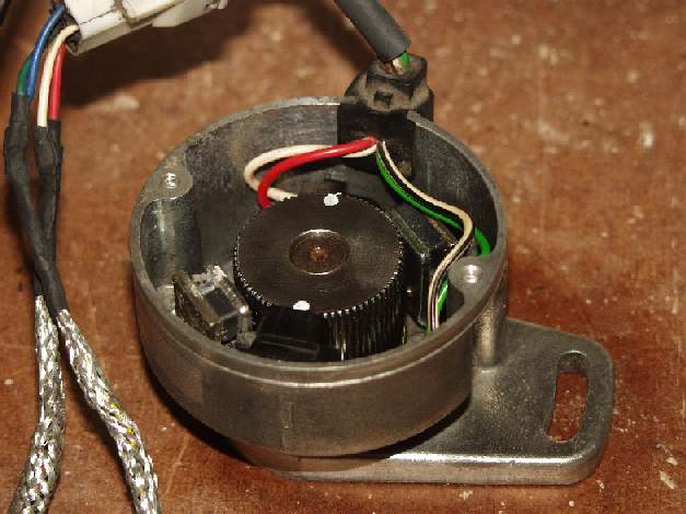
a modified CAS, with 72-2 wheel inside. The 72-2
wheel at 1/2 speed acts identical to a 36-1 on the
e-shaft, so the EDIS modules are happy. I moved the
two stock Mazda VR sensors slightly to give a fixed
split of about 5 degrees between leading and trailing.
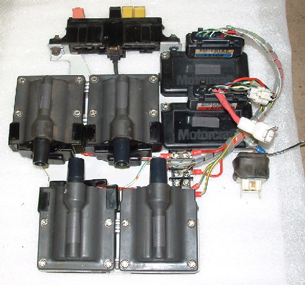
I'm firing four individual coils taken from the
trailing coil packs used on 2nd gen RX7's.
Roger.
I can design and build conditioning circuits.
I think it will start fine on fixed timing. As I recall
Tracy used fixed timing on his early EFI systems. The rotary engine
has a lot of rotational inertia. Particularly with a prop.
Hand propping it would be another matter. Klaus (LSE) uses
a retard for hand propping his O-200.
So the tach circuit and early software in the 68HC908 require
36 pulses per rev? If not 36 how many as I can plasma cut another
steel wheel and mag pickup just for the tach circuit
if necessary. I kind of hate to butcher a perfectly good CAS.
Also a mag pickup could look at the starter ring gear and use a
divide counter. Plus this would work on an RX8 engine with
no CAS.
BTW way back when I used an external 16 bit counter controlled by
a external clock driven hardware interrupt to use as a tach circuit.
The interrupt routine disables the counter, reads it into
the processor, clears the counter and reenables it.
Simple to do if you have a couple of extra 8 bit ports lying
around. The interrupt period was chosen to read the counter
directly in packed BCD RPM. This almost totally off loads
the CPU for tach calculations. A lot of this hardware
is built into some of the more powerful single chippers
such as the 68K 32 bit series from Motorola.
All outlined in my 1979 IEEE paper.
Microprocessor-Based System for Roll-Down and Acceleration Tests
by D.K. Lynn, C.R. Derouin, and Paul Lamar
Los Alamos Scientific Laboratory
Published in IEEE Proceedings 29th Vehicular Technology Conference
(The technical details of the road test system.)
Arlington, Illinois, March 28-30, 1979
I still have some of the hardware lying around as well as the
6502 source code.
I have a rotary table and end mill.
Thanks again Roger.
Paul Lamar ...No rotor no motor.
The Rotary Engine NewsLetter. Powered by Linux.
ACRE NL web site.
http://www.rotaryeng.net
Copyright 1998-2006 All world wide rights reserved.