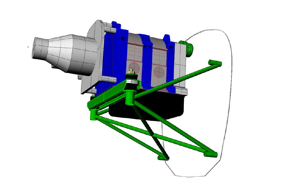
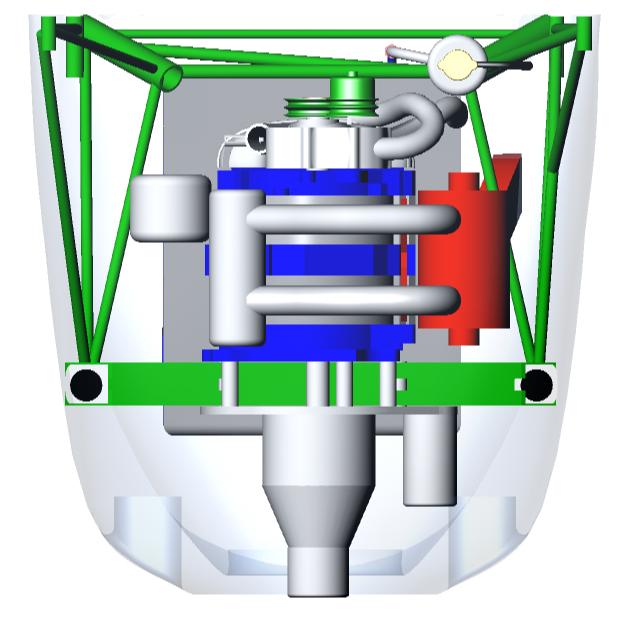
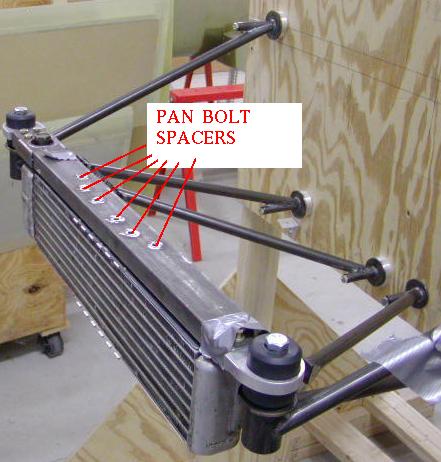
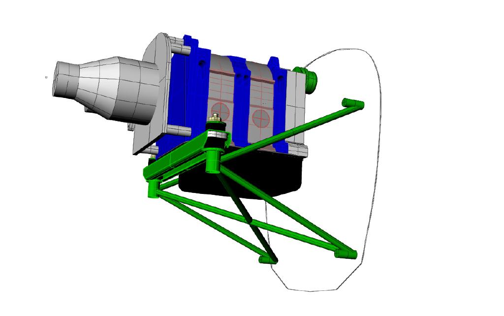
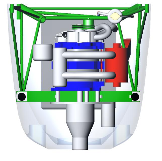
Here is a force diagram and stress calculations
on two motor mount designs.
The size of the arrows are proportional to the loads.
The stress on the lower tube of the first diagram would
not be a problem for 4130 tubing because it is short
and unlikely to buckle. Max allowable stress on 4130 is
66,000 psi. If it were 30 or 40 inches long,
however, buckling would be a severe problem at a
compressive load of 5474 pounds. As shown it is
more a problem for the hard points on the firewall
at 5400 pounds each. Particularly for a composite
or an aluminum firewall. Steel tube fuselages
could deal with it no problem.
The second diagram is what you should strive for.
This illustrates why you should keep the hard points
on the firewall as widely separated as possible.
Paul Lamar ...No rotor no motor.
Please help me understand what the influence of a third tube
has on the tension and compression at the 900# load. Does that
third tube that you advocate for the Schertz beam mount point
take some of the tension and compression loads? Is it half
the compression load or does it not have any
influence on these loads?
Terry Adams
I think you are talking about the lateral X bracing.
It does take some of the compression loads no question about it.
In the case of the RV10 mount in question I assumed
the lateral bracing tubes took a full half of the load from each
side as they do not converge in the center of the
firewall. They go back at a modest angle. They do
not form an X.
In the RV10, and Kis Cruiser for that matter,
there are hard points on either side of the nose gear
firewall mount suitable for lateral bracing. This assumes
of course the firewall is a very stiff panel not prone to
deflection. The same thing is true for RV4, RV6 and Tailwind
mounts that use Tailwind type landing gear. In these cases
the lateral bracing take a higher percentage of the compression
load. In these last cases they are feeding the lateral loads into
another space frame sub system. IMHO it takes a 3D analysis to
determine the exact amount of the compressive load they
do accept.
I ignore the compression contribution of the lateral bracing when
I design the mount. This is a conservative approach and
it under estimates the real strength of the mount.
I add lateral bracing, unlike some other designers,
to take the lateral inertia load developed by the mass of
the engine when the rudder is kicked and or a sudden
yaw develops from a gust or turbulence that would
otherwise cause the engine mount to deflect laterally.
Weight here is not an issue as .049 wall 4130 5/8 inch
tubing weighs only .3 pound per foot.
I use an X as it does not require a cross tube
from the right rubber mount cup to the left rubber mount
cup. A simple diagonal would require such a cross tube.
Those V shaped lateral braces I mentioned above also
do not require the cross tube.
The cross tube would take up valuable space needed
to get air into the top of the radiator core.
Air should go in the top of the rad and out the bottom
but that is another story. The firewall provides the needed
connection between the two back tubes of the X.
These mount design you see here have been well thought out
over a period of seven years.
Paul Lamar
The Rotary Engine NewsLetter. Powered by Linux.
ACRE NL web site.
http://www.rotaryeng.net
Copyright 1998-2006 All world wide rights reserved.