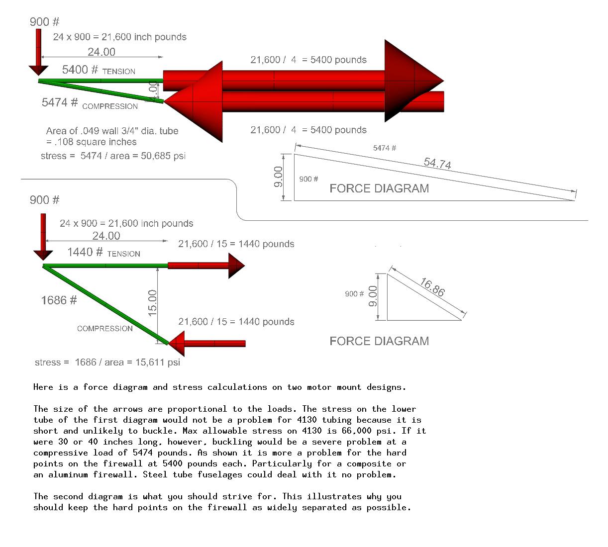
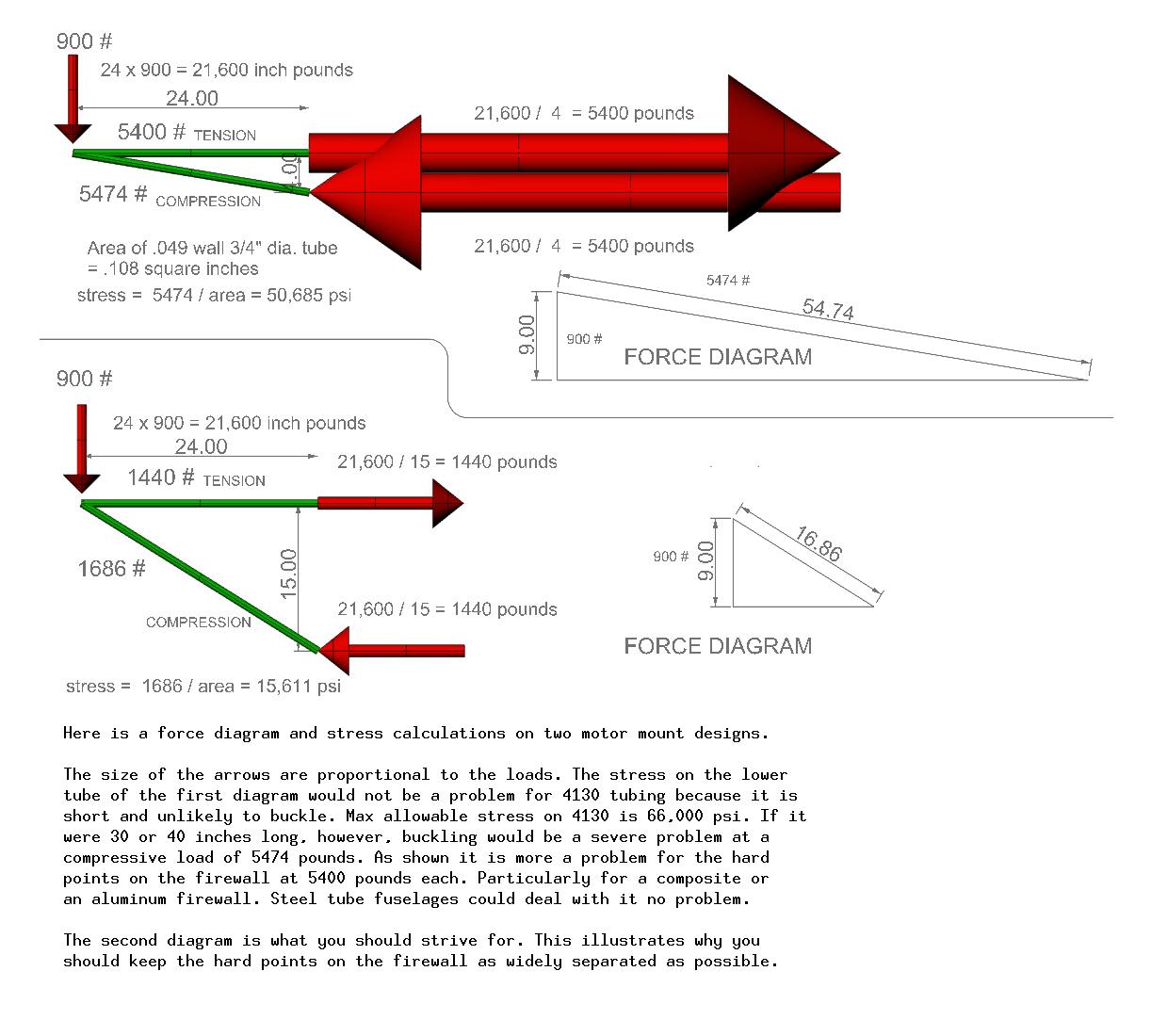
Here is a force diagram and stress calculations
on two motor mount designs.
Hi Paul,
I have not been a structural engineer for 40 years, but on checking
your math in the first diagram, I get 2400 lbs tension (21600/9) and
2563 lbs compression (2400 X 25.63 / 24). I think the error is the
dimension between top and bottom pin joint.
Also, your #2 force diagram has a typo, the vertical distance should
be 15, not 9. I agree with your #2 math.
BR, Dave McC
Taking moments around the the top tube where it intersects
the firewall I get 24 inches times 900 pounds or 21,600
inch pounds. Since the points are 4 inches top to bottom
apart each force is 21,600 / 4 or 5400 pounds.
There is a vertical (y direction) shear load on the fire wall
of 900 pounds (not shown) as all forces in a free body diagram
must equal zero. In the horizontal direction (x) all forces
must also equal zero so the lower 5400 pounds is balanced by
the upper 5400 pounds.
Drawing a scale (one inch equals 100 pounds) right triangle
diagram with the 900 pounds (9 inches) as the vertical leg and
and 5400 pounds (54 inches) as the horizontal leg yields
an hypotenuse length of 54.74" or a load of 5474 pounds in the
diagonal tube in the upper mount.
I did make a slight error in drawing the the second force diagram.
The load is 1695 and not 1686 pounds.
Looks to me like everything else is OK. Both mounts have a 900 pounds
down load.
--
Paul Lamar ...No rotor no motor.
The Rotary Engine NewsLetter. Powered by Linux.
ACRE NL web site.
http://www.rotaryeng.net
Copyright 1998-2006 All world wide rights reserved.