Here is a force diagram and stress
calculations
on two motor mount designs.
Hi Paul,
I have not been a structural engineer for 40
years, but on checking
your math in the first diagram, I get 2400 lbs
tension (21600/9) and
2563 lbs compression (2400 X 25.63 / 24). I
think the error is the
dimension between top and bottom pin joint.
Also, your #2 force diagram has a typo, the
vertical distance should
be 15, not 9. I agree with your #2 math.
BR, Dave McC
Taking moments around the the top tube where
it intersects
the firewall I get 24 inches times 900 pounds
or 21,600
inch pounds. Since the points are 4 inches top
to bottom
apart each force is 21,600 / 4 or 5400 pounds.
There is a vertical (y direction) shear load
on the fire wall
of 900 pounds (not shown) as all forces in a
free body diagram
must equal zero. In the horizontal direction
(x) all forces
must also equal zero so the lower 5400 pounds
is balanced by
the upper 5400 pounds.
Drawing a scale (one inch equals 100 pounds)
right triangle
diagram with the 900 pounds (9 inches) as the
vertical leg and
and 5400 pounds (54 inches) as the horizontal
leg yields
an hypotenuse length of 54.74" or a load of
5474 pounds in the
diagonal tube in the upper mount.
I did make a slight error in drawing the the
second force diagram.
The load is 1695 and not 1686 pounds.
Looks to me like everything else is OK. Both
mounts have a 900 pounds
down load.
------------------------------------------------------------------------
Paul,
Your calculations are correct. The confusion
lies in mixing the
physical dimensions that define the geometry
with the force vectors that
result from the external loads. Years ago when
I taught EIT and PE exam
review courses, this error cropped up a lot
because of the "get it done
quickly" methods that were espoused in the exam
review books.
Aubrey
When I went to school they did not teach this
graphical method.
Too hard to measure a pencil drawing. With 2D
and 3D CAD programs
it is easy to draw triangles to accurate scale
and use
the "aligned dimension" ability to estimate the
load. That makes
it more intuitive and quicker than doing the
trig.
BTW do you now of any 3D space frame programs
that all you need
do is feed it a DXF or iges and it calculates
the loads? Does
Solid Works do that? That would be a great
thing to have for the
more complicated "bird cage" motor mounts that
occasionally show
up. The simple 2D ones are easy to do with the
graphical method.
Takes more time to explain it than do it. A 3D
version is
not so easy.
Paul Lamar ...No rotor no motor.
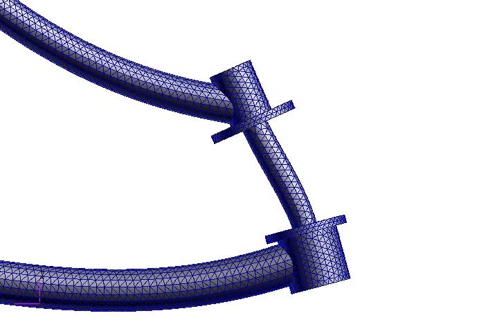
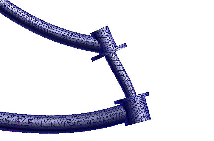
SolidWorks will "in effect" do this via another
program [ provided with SolidWorks Office Pro]
called CosmosDesigner. Its an FEA program. The
bare bones version of SW comes with
CosmosExpress
which is a part based FEA program. If you can
assume the welds won't fail you can modeling the
mount in 1 pc and then load the mount up in
Cosmos
and get decent results, its a good rule of thumb
if nothing else.
Jarrett
Good news. From now on Jarrett we will send you
our mounts
for a free FEA :)
Looks like I am forced to learn SW :(
--
Paul Lamar ...No rotor no motor.
Send away, I'll be happy to help where I can!
Jarrett
I am mostly kidding. These mounts are so light weight
and so strong it hardly pays to optimize them. It is more a
function of the welders ability to weld thin .049 wall 4130
tubing.
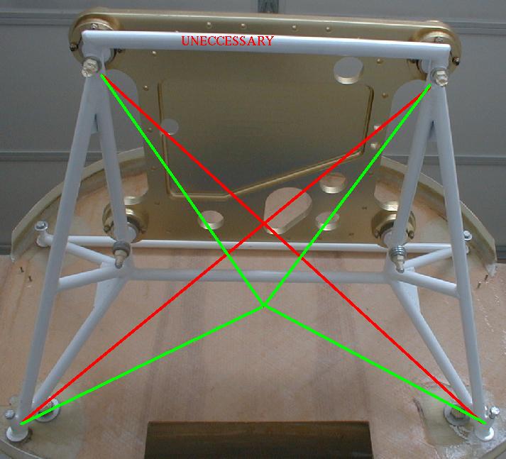
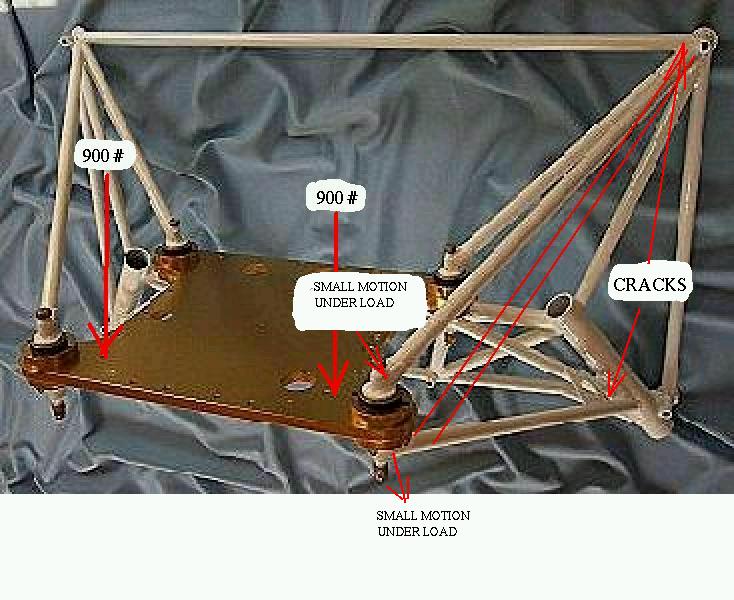
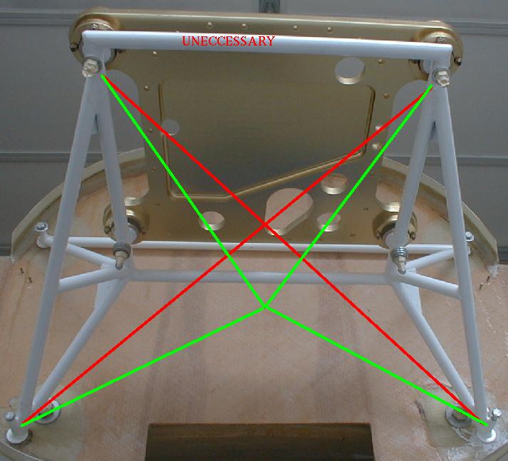
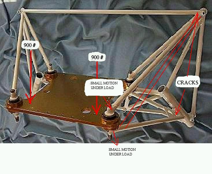
That does not mean ALL the mounts on the market
are this good. Some are so poorly designed (violating
the space frame rules) that they sorely need analyzing.
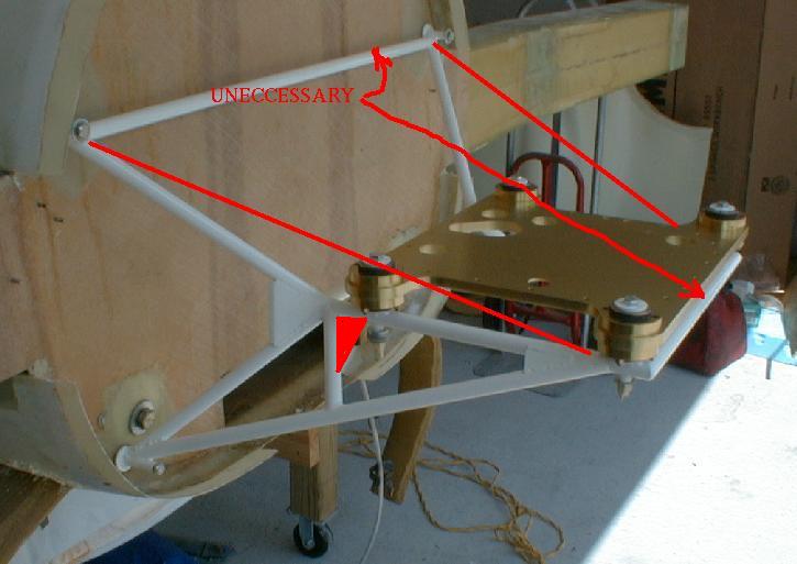
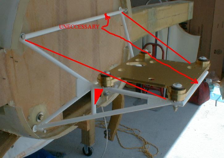
Here are some bad examples from the past.
In the last jpg the lower tubes are not in the same
plane as the horizontal tube so they tend to be
deflected outward and and upward by a wedging action.
Only the bending stiffness of the adjacent tubes keep
them from doing so and the mount catastrophically
collapsing. The answer is an X in the bottom.
--
Paul Lamar ...No rotor no motor.
The Rotary Engine NewsLetter. Powered by Linux.
ACRE NL web site.
http://www.rotaryeng.net
Copyright 1998-2006 All world wide rights reserved.