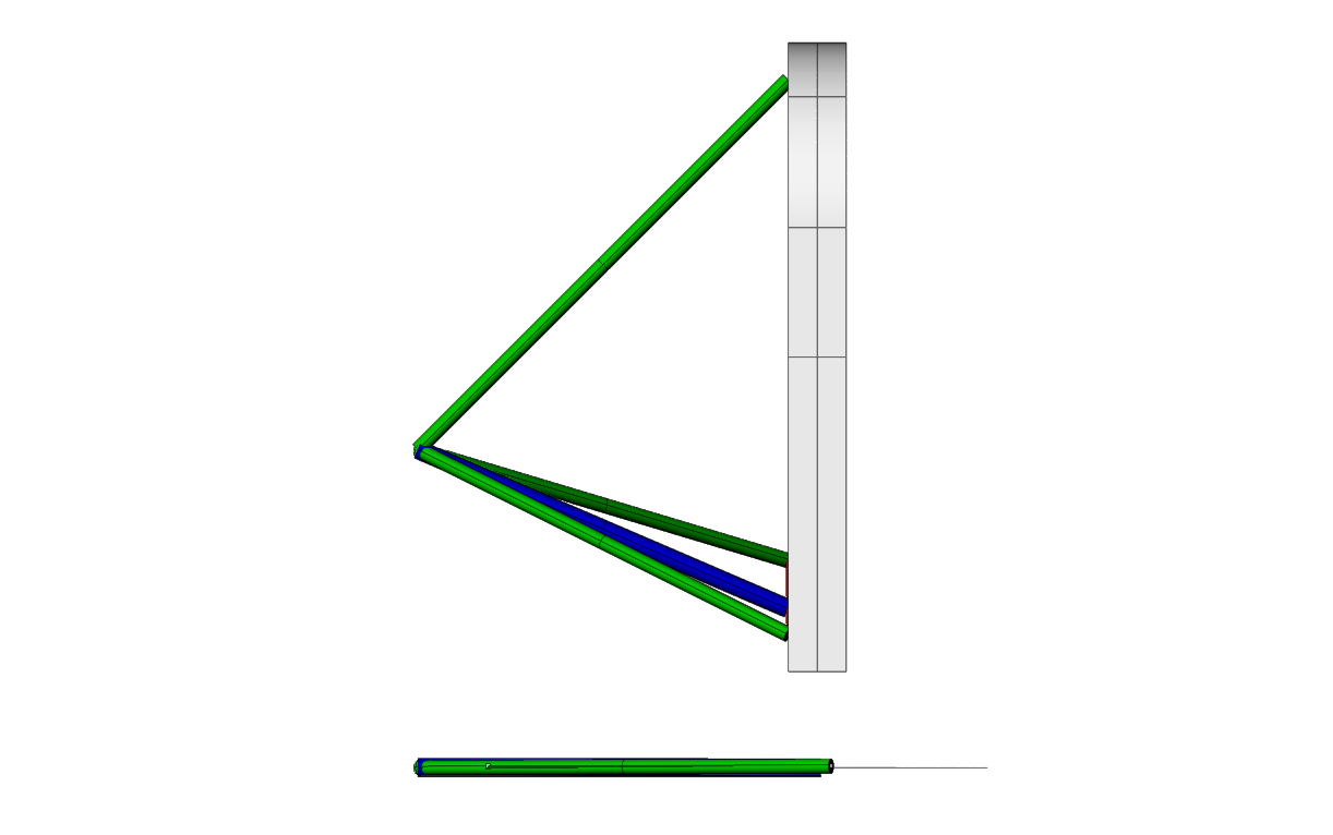
I call this method the virtual tube method
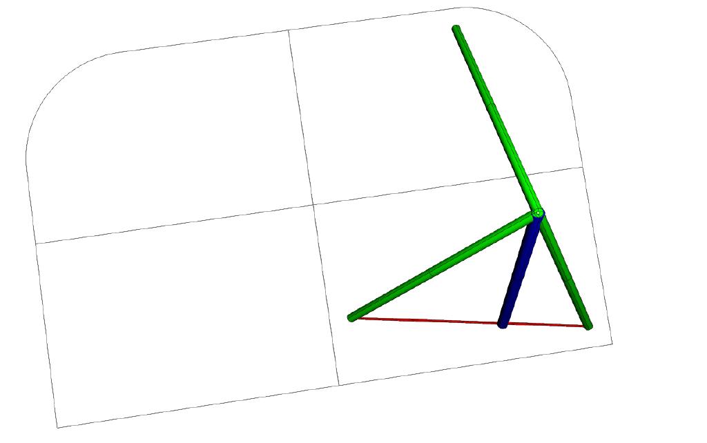
The two lower tubes are replaced by an imaginary tube.
The blue one in these 3D.
The blue tube end point is found by drawing a straight
red line between the hard points on the firewall and placing
a mark on that line that is in the same plane as the upper
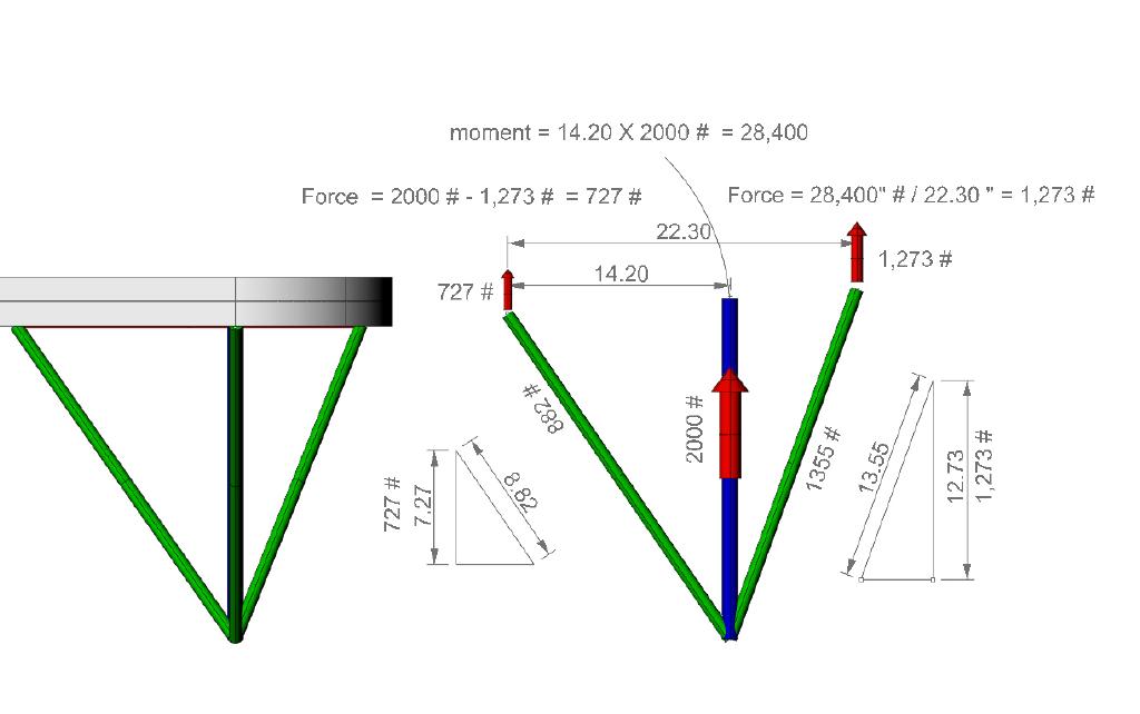
tube. At that point you calculate the loads in the
lower virtual tube using the simple graphical method.
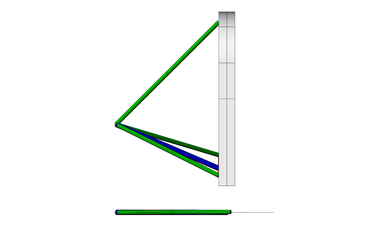
The three tubes, the virtual tube and the two real tubes,
form a triangle in a single plane. You flatten this triangle
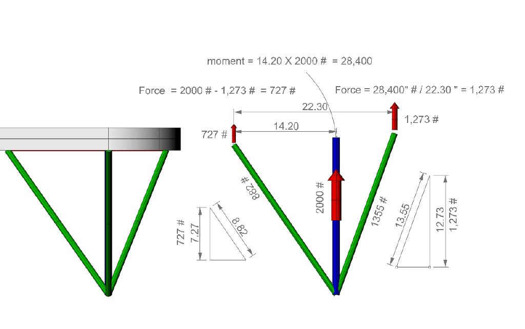
out in the horizontal plane and proceed to calculate the
percentage of compressive load each real tubes shares
using the moment or See Saw method.
These 3D's are largely self explanatory about this procedure.
This is easier to do if you have a 3D CAD program like
Rhino or Solid Works
It beats using a full blown FEA program like the
Dutch FEA program. If Quick Basic was still around
I could write a program that would do this.
Perhaps a spread sheet program could be written
to do this as well.
Paul Lamar ...No rotor no motor.
The Rotary Engine NewsLetter. Powered by Linux.
ACRE NL web site.
http://www.rotaryeng.net
Copyright 1998-2006 All world wide rights reserved.