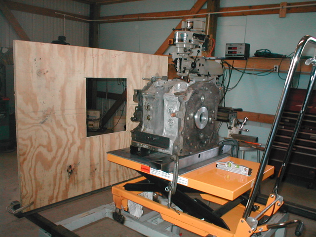
Paul, here is a pic of the engine mount fixture I am working on.
The base is a hydraulic lift table which makes it easy for me to set
the engine on/above/below the thrust line. The piece of plywood
with a hole in it is only there to demonstrate how the firewall will
be positioned. The rack it sets on can be slid in or out for any
firewall clearance we want.(The S-beam in this photo is Randy's 22.2
inch.) The machined aluminum ring is the beginning of a bracket that
will mount a torpedo laser that will fire straight down the thrust
line and on to the plywood firewall. That is the laser setting on
the table
If we want to angle the engine off thrust, where is the pivot
point? Center of engine? Prop flange face? I have often wondered
about this.
The engine is setting on a piece of quarter inch steel plate. I
intend weld brackets on the plate and bolt the engine to it. If we
want to angle the engine, we can do so by shimming the plate. Would
it be possible for you to use the point where the laser points on
the firewall to tell me how to shim the engine? In other words you
would tell me to set the laser x distance from the horizontal thrust
and y distance from the vertical thrust.
This fixture is intended to fix the short comings of first fixture
which was impossible to adjust in any direction except fire wall to
prop flange where it did have a range but not enough.
Jerry
Looks real good. Good idea with the laser.
Prop flange center as that brings the flange out
in the center of the cowl regardless of the off set angle or
down thrust angle. That should be our reference point.
Paul Lamar
The Rotary Engine NewsLetter. Powered by Linux.
ACRE NL web site.
http://www.rotaryeng.net
Copyright 1998-2006 All world wide rights reserved.