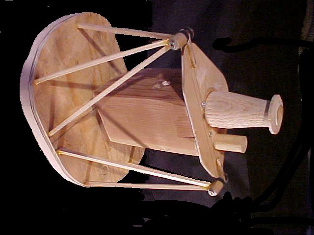
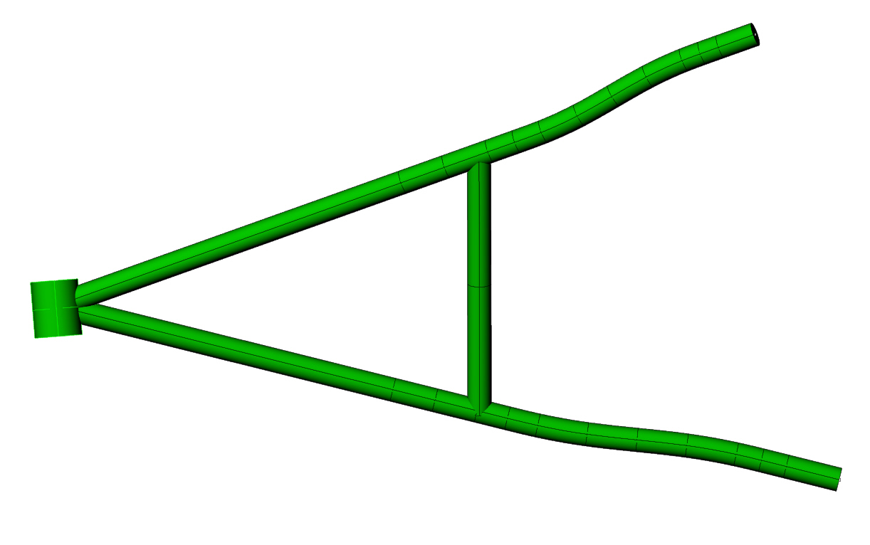
This is the start of my Thorp T18 engine mount tacked together. When it
comes back from the welder I will tack together the bottom cross pieces.
Am I leaving anything out?? Karibian
I assume those verticals are just temporary as welded them
in would hurt and not help. I cannot see the lower hard points
connections so I cannot comment on those.
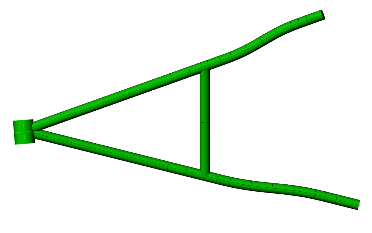
The upper connections are inadequate. You need a more traditional
cup type connection where the bolt is in a blind tube. See the 2D
sketch attached. The angle will crack sooner or later. You also will
need an X in the bottom of course. See the attached 3D.
If you have the schertz beam I would bolt it on before
the welder did any final welding. If not make a temporary
schertz beam simulator so the mount does not warp out
of alignment with the schertz beam.
Paul Lamar ...No rotor no motor.
It seems that the verticals help the lower tube from buckling under
compression loading, though additional tubes would need to also be
installed off-axis from the existing ones (horizontally).
Matt-
It would become another "bay". That bay would then become
un triangulated. It would "lozenge" to use a popular technical
term :) When you start adding tubes you have to add more
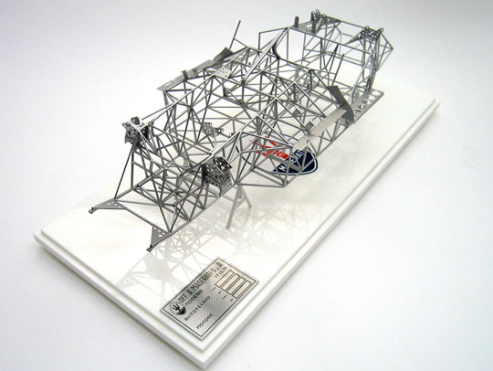
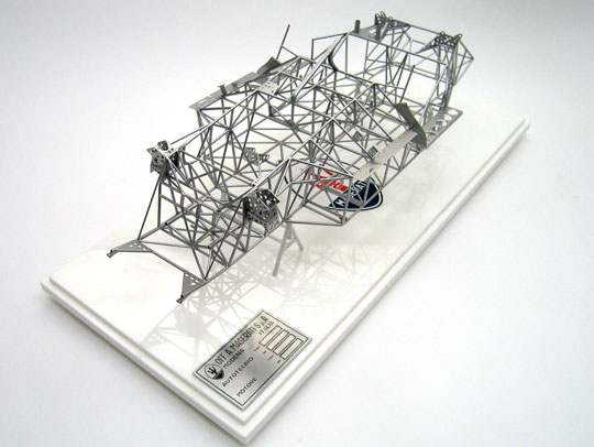
and more and you wind up with a Birdcage Maserati chassis :)
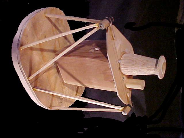
You can see this if you make a 1/4 scale balsa or welding rod
model and apply some load. To stabilize the lower tubes from buckling,
(if for some strange reason you can not go up on the tube OD),
break the bay into two or more triangles.
On the other hand if the mount is already made and someone screwed
up on the design and did not make the diameter of the tubes large
enough or made them too long and you needed to add a band aid
to prevent buckling then make the supporting tubes small in
diameter(less than 1/2 inch) and they will deflect locally rather
than the main tubes. Also a flexible connection can be made using
rubber or ball joints that will stabilize the tubes in buckling
but not add stress concentrations.
Needless to say it is best to design the bloody thing right from
the get go calculating the buckling possibilities. This
leads to a simple and elegant motor mount.
Here is a 2D. I'll add this to my bad details collection.
Paul Lamar ...No rotor no motor.
The Rotary Engine NewsLetter. Powered by Linux.
ACRE NL web site.
http://www.rotaryeng.net
Copyright 1998-2006 All world wide rights reserved.