Do yourselves a favor and search out an Enstrom helicopter to study
their system. It has been in use for a very long time with great
success. Enstrom uses the belt as the clutch and this solves the
tension
problem for Enstrom. The polyV provides damping of torque pulses.
The
system should be no more complex nor heavier than a cog belt
system with
the exception of the tensioning device.
This past Saturday I examined the "Belted Air Power" unit on a V8
engine. It is quite clean and in use for a long time. However I want
to use the polyV belt system as I think there is less risk of
catastrophic failure. With the cog belt improper tensioning can
raise
havoc with the belt teeth. The cog belt may not provide the damping
qualities of the polyV belt.
Bob Y
There are way more Robinsons flying then Enstrom :)
Probably a 100 times as many :)
The V-ribbed provides damping too. Probably it is more efficient
than a poly V as the belt is thinner so there is less
flex and heat build up. However not recommended for a clutch type
helicopter application.
Paul Lamar ...No rotor no motor.
----------------------------------------------------
Bob,
That's my thinking exactly -- I would much rather go with v-ribbed, or
even multi-v, than cog belt.
The difference is that an improperly tensioned v-belt will merely slip,
while the cog belt will quickly self-destruct.
A cog belt will still provide some torsional damping, just as a chain
drive will, but v-belts are better in this regard too.
I really can't understand why cog belts are so popular. The only time
you really need them is when you need synchronicity, which you don't
with a prop drive. Otherwise they bring a lot of negative baggage.
Regards,
Gordon.
Simple question leads to a really interesting discussion. What belt
section and width (# ribs) is it going to take to transmit the ~200 hp?
What kind of center distance can be used? What kind of static tension
is required?
Ken Bauman
One more question. 200 HP at what RPM?
------------------------------------------------------------------------
There is some confusion here. Paul's design chart was posted in
reference to the turbo compound drive that could return as much as 60hp
to the e-shaft. The red X is the design point for 60hp at 6500rpm. The
J section belt is the thinnest one and according to the Gates design
manual can handle about 2hp per rib at this speed with a 5" diameter
sheave. At this rpm the linear belt speed is about 142ft/sec. Since
Power = (force)x(velocity) the belt tension required to transmit the
power is about 232 lb. A reasonable guess for the coefficient of
friction between the belt and the sheave for this situation may be about
0.5. This would mean that to transmit the 232 lb friction force to the
belt we would need a perpendicular (normal) force between the belt and
the sheave of about 460 lb. At a belt speed of 142ft/sec the
centrifugal force on the belt is substantial as it wraps around the
sheaves and it is in the opposing direction to the normal force we need
to prevent slippage. Putting this data into the belt calculator on the
Hutchinson web site that was mentioned a few days ago gives a required
belt tension in the range of 2000 lb to 2700 lb. So, a large amount of
excess belt tension is required to balance the centrifugal force. This
design point is near the upper limit for the capacity of the J section belt.
Suppose we apply similar reasoning to a PSRU using friction belting.
Let's assume an engine power of 300hp at 8000rpm with a reduction ratio
of 3:1 in the PSRU. A reasonable sheave combination would be 3.5"
diameter at the engine and 10.5" diameter at the prop shaft. This
engine sheave results in a belt speed of 122ft/sec and a driving tension
in the belt of 1352 lb. Now we have to maintain a normal force between
the belt and the sheave of about 2704 lb. Undaunted by this number, we
continue. From the Gates design manual it looks like if we had a 40
rib L section belt it may be able to handle this power level (although
the maximum recommended design speed is only 4000rpm for this belt and
sheave size, and, a 40 rib belt would be more than 7" wide). The mass
ratio between the J section belts and the L section belts is 3.7:1;
ie, the L section belt weight per inch is 3.7 times that of the J
section belt. Since the the centrifugal force scales linearly with belt
weight and scales with the square of the belt speed, we can conclude
that a reasonable estimate for the belt tension would be to use the
tension range for the turbo-compound belt above and scale it by the
ratio (3.7)x(122^2 /142^2 ) which gives a tension range of 5500 lb to
7200 lb.
Admittedly, this analysis is only a rough approximation, but it shows
why these belts work well for high power only if the speed is low
enough. Toothed belts are the only reasonable choice for a belt drive PSRU.
Aubrey
I think you are being a little pessimistic about the coefficient
of friction. I think it closer to one than it is to .5.
Also I the belt wants to go circular when going over two pulleys
so I am not so sure it is easy to calculate the centrifugal
force on the belt. Going circular tends to increase the
normal force on the pulleys in certain areas I would think.
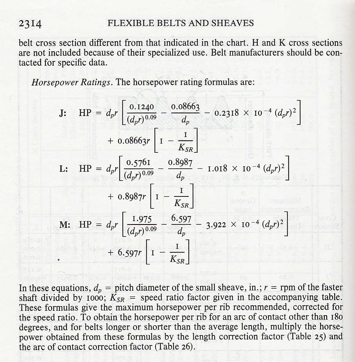
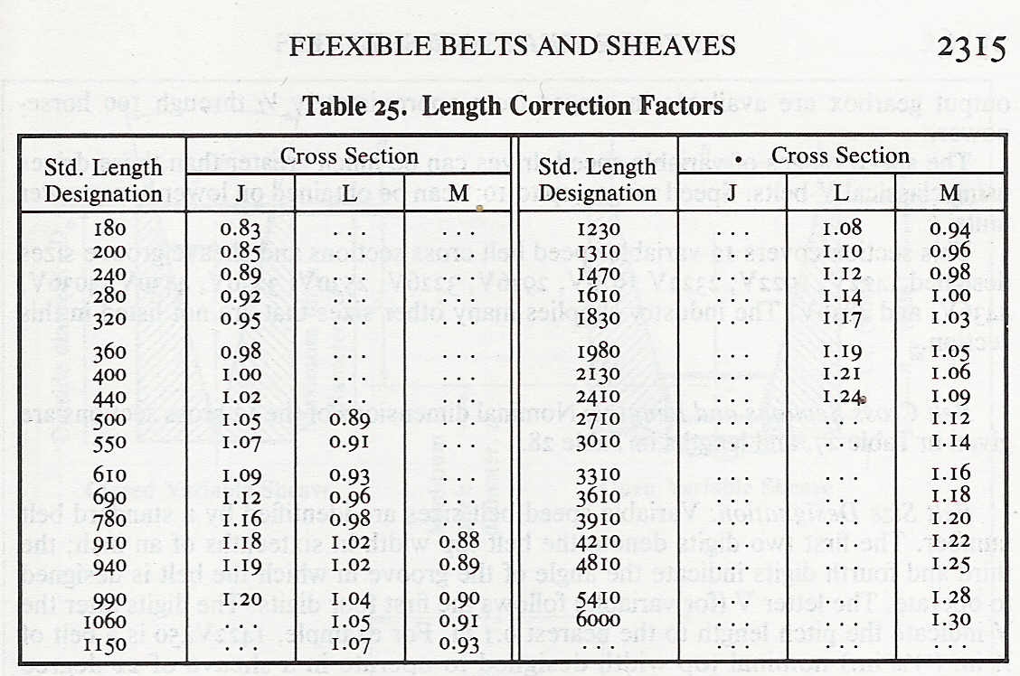
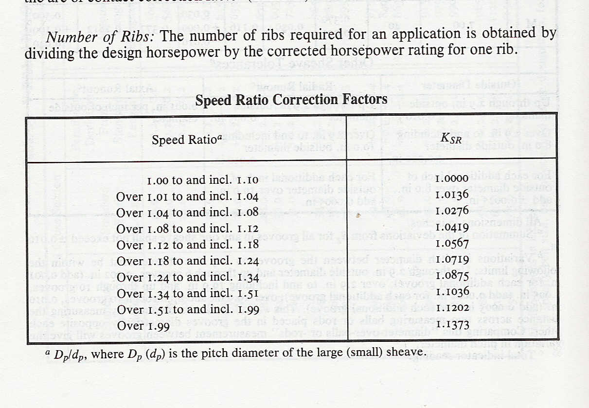
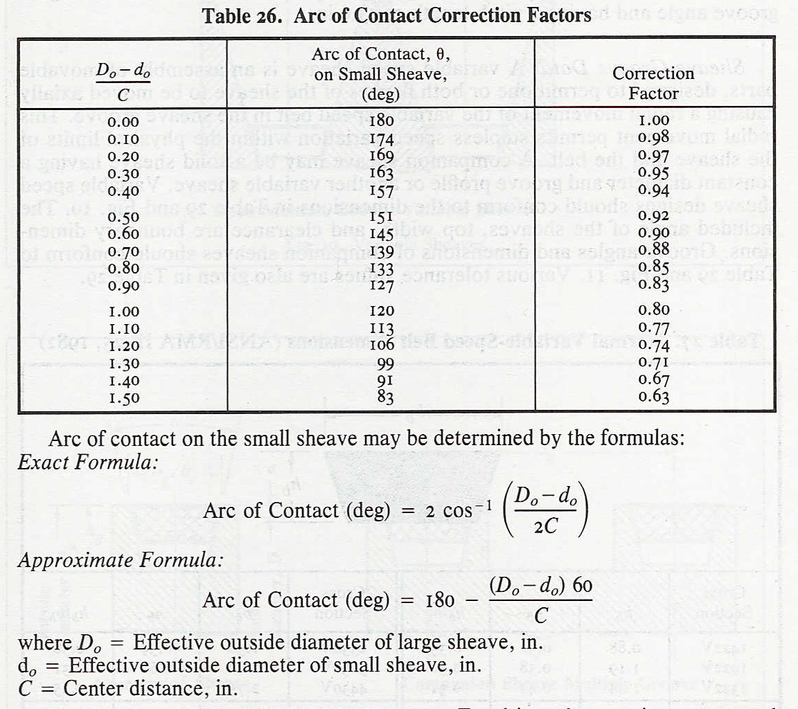
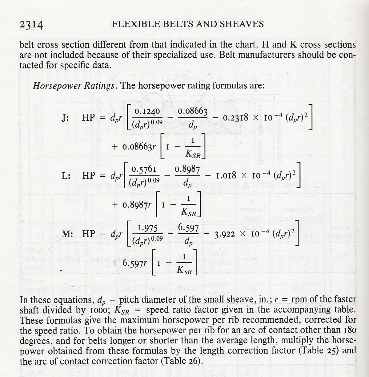
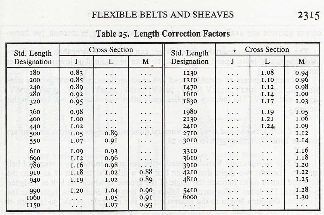
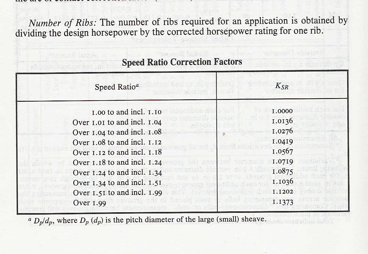
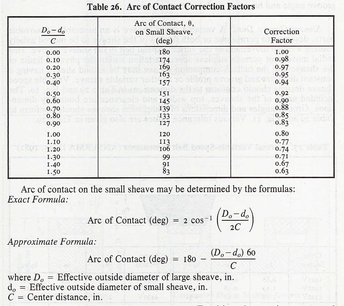
Machinery's Hand book also has the HP formulas
as a function of pitch diameter and correction factors
for arc of contact, speed and belt length. I'll scan
some of this in later.
Machinery's Hand Book is usually pretty conservative.
--------------------------------
Try these formulas Aubrey.
Paul Lamar ...No rotor no motor.
The Rotary Engine NewsLetter. Powered by Linux.
ACRE NL web site.
http://www.rotaryeng.net
Copyright 1998-2006 All world wide rights reserved.