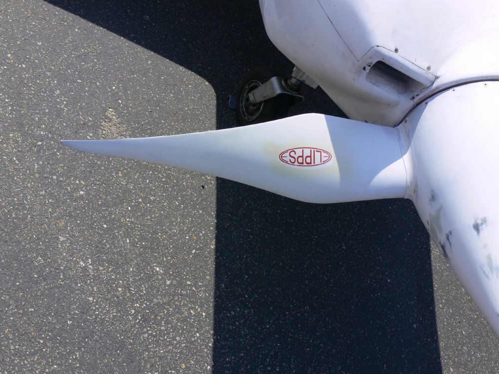
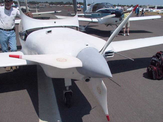
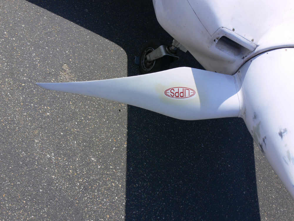
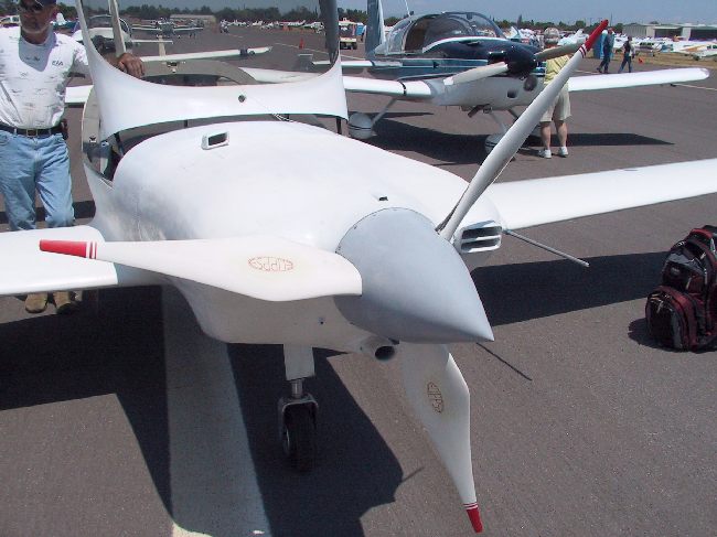
I am fascinated by Paul's prop design
and attempting to fully understand the rational behind
it.
I refined my QB program a bit further.
I also found a serious error as I was not
multiplying the lift function by the lift coef.
I also corrected the thrust for the thrust
in the direction of travel and not perpendicular
to the blade cord. That made a huge difference
in the thrust developed near the root of the blade
due to the unfavorable blade angle despite the seven
inch cord width. I also added
torque increment loads for each blade segment and totaled
them up. I got a ridiculous low over all torque load
for the blade of six foot pounds so there could
be a mistake in there some place. Also I may have
underestimated the operating lift coef. at only .5
and consequently also the drag coef. at only .01.
As the lift coef. is increased the drag coef. increases
faster.
Paul, what do you figure the lift coef. is?
Another possibility is the blade tip vortex torque load
which is CsubL squared divided by the aspect ratio
of the blade times pi times the length of the blade.
Could be considerable. In fact I think Paul mentioned that.
Hopefully some one on here will see the error of my ways.
Never the less this simple program is approaching usefulness.
Also sorts of trade offs can be tried such as wider blades
running at a lower pitch or lift coef..
BTW the prop torque generated by the rotary through the 2.85:1
PSRU is on the order of 430 foot pounds so I am way
off.
RPM = 2700 MPH = 200 Lift Coef. = .5 Drag Coef. = .01 Air density = .0026
Radius Tan V Angle Cord V Cord Seg Area Seg Thrust Seg Torque
Inches MPH Deg MPH Inch Sq. feet pounds pounds
3.00 48.2 76.5 206 7.20 0.150 1.93 0.04
6.00 96.3 64.3 222 6.60 0.138 3.82 0.09
9.00 144.5 54.1 247 6.00 0.125 5.79 0.15
12.00 192.7 46.1 278 5.40 0.112 7.83 0.23
15.00 240.9 39.7 313 4.80 0.100 9.80 0.32
18.00 289.0 34.7 351 4.20 0.087 11.56 0.42
21.00 337.2 30.7 392 3.60 0.075 12.89 0.52
24.00 385.4 27.4 434 3.00 0.063 13.59 0.61
27.00 433.5 24.8 477 2.40 0.050 13.45 0.67
30.00 481.7 22.5 522 2.40 0.050 16.33 0.88
33.00 529.9 20.7 566 1.80 0.038 14.63 0.86
36.00 578.0 19.1 612 1.20 0.025 11.49 0.73
Total Thrust Pounds = 123 Total Torque Foot Pounds = 6
OPEN "C:\qb\props\pitch200.dat" FOR OUTPUT AS #1
CLS
DIM Cord(25)
Thrust = 0
Torque = 0
AirDen = .0026
MPH = 200
CsubL = .5
CsubD = .01
RPM = 2700
PRINT #1, "RPM ="; RPM;
PRINT #1, " MPH ="; MPH;
PRINT #1, " Lift Coef. ="; CsubL;
PRINT #1, " Drag Coef. ="; CsubD;
PRINT #1, " Air density ="; AirDen
PRINT #1,
PRINT #1, "Radius Tan V Angle Cord V Cord Seg Area Seg Thrust Seg Torque"
PRINT #1, "Inches MPH Deg MPH Inch Sq. feet pounds pounds"
FOR radius = .25 TO 3 STEP .25
RadiusInch = radius * 12
PRINT #1, USING "##.##"; RadiusInch;
TangVelFPS = (6.28 * radius * RPM) / 60
TangVelMPH = (TangVelFPS * 60) / 88
PRINT #1, USING "#####.#"; TangVelMPH;
tan1 = MPH / TangVelMPH
angleRAD = ATN(tan1)
angleDeg = (angleRAD * 57.295)
PRINT #1, USING "######.#"; angleDeg;
CordVel = (TangVelMPH ^ 2 + MPH ^ 2) ^ .5
PRINT #1, USING "######"; CordVel;
READ Cord
PRINT #1, USING "####.##"; Cord * 12;
SegArea = .25 * Cord
PRINT #1, USING "#####.###"; SegArea;
ThrustInc = CsubL * SegArea * (CordVel) ^ 2 * AirDen
'sin=opp/hyp
angle2Deg = 90 - angleDeg
angle2RAD = angle2Deg / 57.295
Thrust2 = SIN(angle2RAD) * ThrustInc
PRINT #1, USING "########.##"; Thrust2;
dragInc = SegArea * CsubD * CordVel ^ 2 * AirDen
TorqInc = dragInc * radius 'foot pounds
PRINT #1, USING "########.##"; TorqInc
Thrust = Thrust + Thrust2
Torque = Torque + TorqInc
NEXT
DATA .6,.55,.5,.45,.4, .35, .3, .25, .2,.2,.15,.1
PRINT #1,
PRINT #1, "Total Thrust Pounds =";
PRINT #1, USING "#####"; Thrust;
PRINT #1, " Total Torque Foot Pounds =";
PRINT #1, USING "#####"; Torque
CLOSE
SHELL "more < pitch200.dat"
END
Paul Lamar ...No rotor no motor.
The Rotary Engine NewsLetter. Powered by Linux.
ACRE NL web site.
http://www.rotaryeng.net
Copyright 1998-2006 All world wide rights reserved.