Paul,
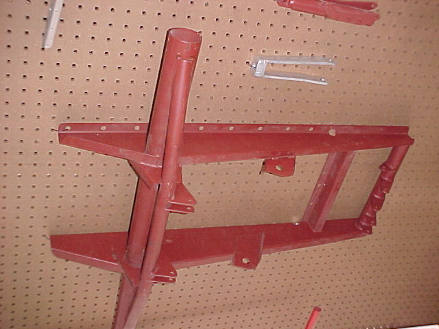
Unlike the schertz beam mount for the rotary, the cg of the engine/prop
is substantially forward of the lower mount bushings. The g loading
moment about the lower bushings would be much greater than is the
case on the rotary schertz beam. I would think the cg of the
Lycoming would be at least 12" away from the bushings. Then a
6g load on the 300 lb engine would be an 1800 lb-ft moment that
the rod ends would have to resist.
Aubrey
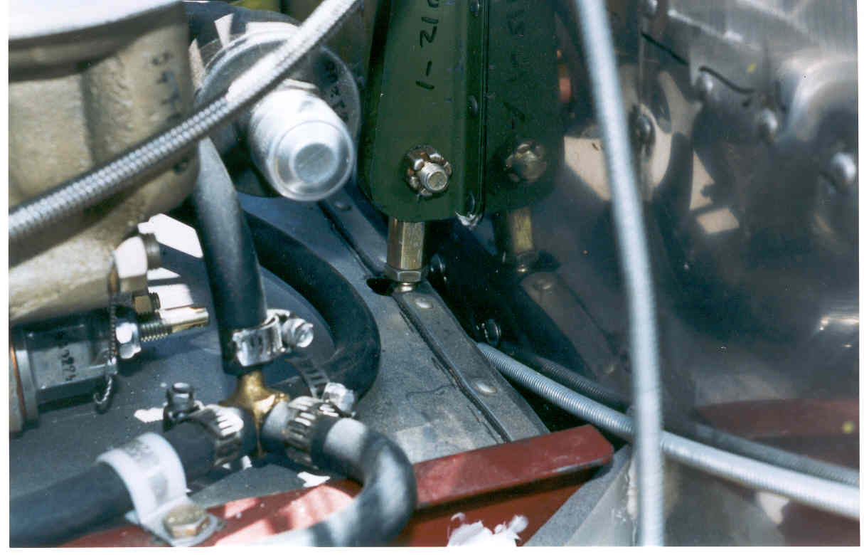
I agree Aubrey but they won't fail. The occasional 6 G
vertical load may bottom them out but won't fail them.
The upper and lower bushing are about a foot apart
vertically so that is 1800 pounds tensile load on both
tubes at 6 G. Each rod end will see 900 pounds at 6 G.
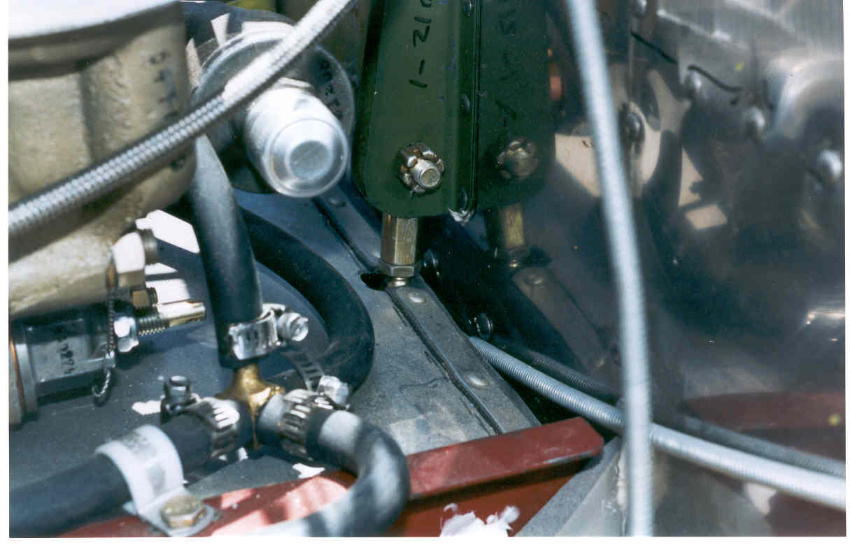
The steel strap surrounding the rubber bushing is at
least .065 thick by 1/2 inch wide. At a yield strength
of 40,000 psi it will take a max tensile load of 1300
pounds. If one wants something more secure one should use
a $6 solid half inch rod end with a tensile rating of
8000 pounds. Just less vibration isolation. Actually
a solid 1/4 inch rod end would do at 1700 pound rating.
The rubber rod end load rating is 270 pounds continuous for
less than a bottomed out mount. The continuous one G tensile
load is 300 pounds total and 150 pounds each rod end.
The other bad thing is the lower two stock rubber bushings
are now catching hell with the total prop torque and vertical
shear load. Consequently they will have a shorter life.
I never said it was a good design :) Just better than
what Crissi had.
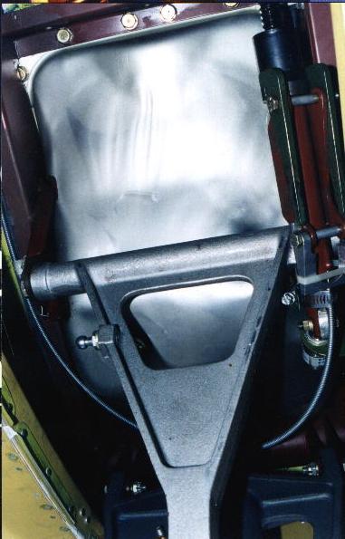
Here is the right and conservative way to do it.
Paul Lamar ...No rotor no motor.
------------------------------------------------
Hi Aubrey,
I just got some more picture of my favorite
kit aircraft. The Jim Griswold designed Questair Venture.
Sure the landing gear has problems but people are fixing that.
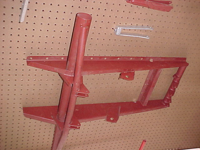
What I liked about it was the motor mount and that is
what we have patterned the rotary motor mount around.
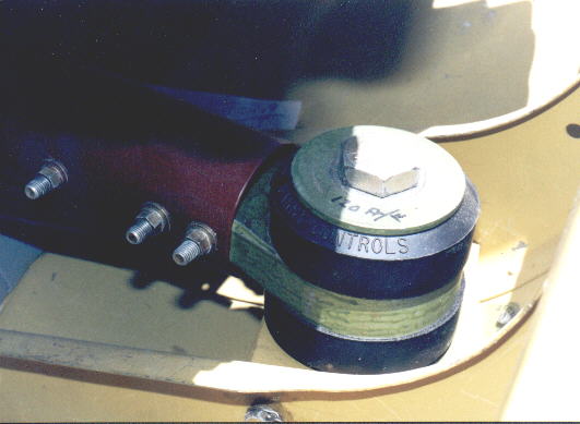
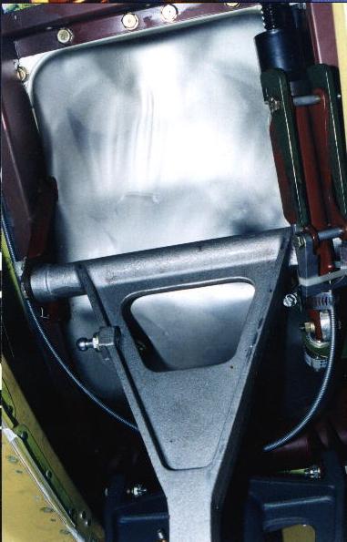
Namely two large rubber bushings widely spaced under
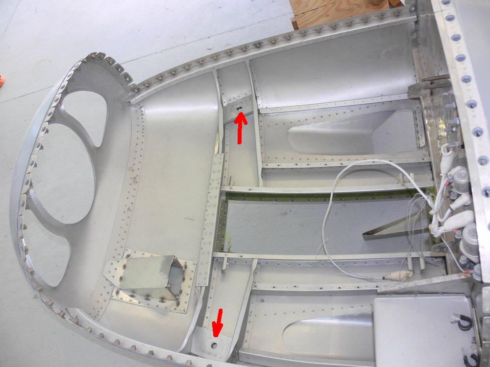
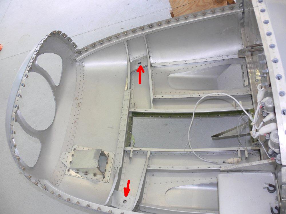
the CG of the engine. Here is a new shot looking down
into the integral lower cowling. Everything you see here
is structural. The two arrows indicate
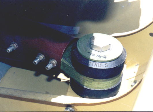
the 1/2 inch bolt holes that hold the same Barry rubber
bushings we use. Not only do these bolts attach the engine
to the airframe but the nose gear loads go into the engine
and then into the airframe through these same bolt holes.
The Barry bushings are rated about 300 pounds but they
too bottom out under the 900 pound 6 G down load in a pull
up. However they don't see 900 pounds in a 6 G hard landing
as most of the inertial load from nose gear goes directly
in the mass of the engine. CLEVER!
Paul Lamar ...No rotor no motor.
The Rotary Engine NewsLetter. Powered by Linux.
ACRE NL web site.
http://www.rotaryeng.net
Copyright 1998-2006 All world wide rights reserved.