>> Giffen Marr wrote:
>>> Paul
>>>
>>> Am I to understand that the TC Drive is to be driven by a
shaft
from the
>>> Turbo compressor? If so, aren't shaft rotational speeds of
60k
to 80k
>>> going
>>> to present a problem?
>>>
>>> Giff Marr
>>> LIV-P/20B 45%
>>>
>>>
>>
>> What problems did you have in mind? This is what I think I
am going
>> to use in the 1/2 inch size.
>>
>
> Paul, you are joking right?
> Mark W.
>
> Opss I forgot to attach it.
>
> --
> Paul Lamar ...No rotor no motor.
Hi Paul,
It was attached the first time.
You don't seriously think you can attach two shafts rotating at
80K with
this do you?
Mark W.
Why not?
--
Paul Lamar ...No rotor no motor.
Balance specs?
Matt-
I don't really know Matt. I'll buy a few and measure the
run out. If greater than what we think we can make we will
make some. However the moment inertia of this shaft is so
much less than the moment of inertia of the compressor rotor
I can't see at this time how it can cause a problem. I could
be way wrong. The input shaft to the gearbox could not be
better supported or more rigid being sandwiched between three
much larger steel rollers at high pressure.
One end of the proposed steel u-joint would be machined to act
as the nut on the compressor end of the turbo charger shaft.
The torque is 3 to 5 foot pounds
so the OD of the connecting portion is larger than necessary
and we may grind it down 3/8" OD to further reduce its
moment of inertia and weight.
I also thought about a flex coupling made from a short
section of 1/2 inch ID Teflon lined SS braided hose and
some sort of clamps. So far I have not come up with a good
clamp that would be balanced on its axis.
Here is an interesting paper on the whirl mode of turbocharger
shafts.
Paul Lamar ...No rotor no motor.
Paul.
Take a look at the flexible bellows couplings at
http://www.rinomechanical.com/shftcoup.htm
The problems of high speed shaft couplings is complex. I would
suggest that these folks are only a starting point. If you manage to
perfect or even optimize a shaft coupling at those speeds, you won't
have to worry about turbo compounding.... you will have solved a long
standing challenge in dynamics, torsional, and vibration, and you'll
be rich.
Don't waste your money on the shaft type shown. It will kill anyone
standing nearby well before it gets to even 10k rpm. (You could set
up an easy test with an air powered die grinder or similar, on your
lathe) It would be like trying to build a good shift linkage using
Craftsman universals.
The turbocharger center section bearing is an unusual animal in that
it is a double film bearing... that is, it has a hydrostatic film on
both the ID and the OD of the bearing shell, cutting the relative
speed of the shaft vs. the shell in half. But it also means that to
work effectively it needs to be free-floating, and able to find its
own rotational center. Any misalignment at the compressor nut skews
the forces and Psssst! the bearing is gone.
Good luck. This is a tricky one.
Reeves Callaway
Thanks for sharing your considerable experience on this Reeves.
What is the failure mode of this kind of u-joint at high speed?
Would silicon nitride ceramic ball bearings in the turbo charger
help? I notice they have become quite popular in turbochargers
and machine tool spindles.
Good suggestion on the air motor. I was thinking about some sort
of testing but I had not thought of an air motor. Sounds
very doable. I don't think my lathe will run fast enough
to be meaningful.
Paul Lamar ...No rotor no motor.
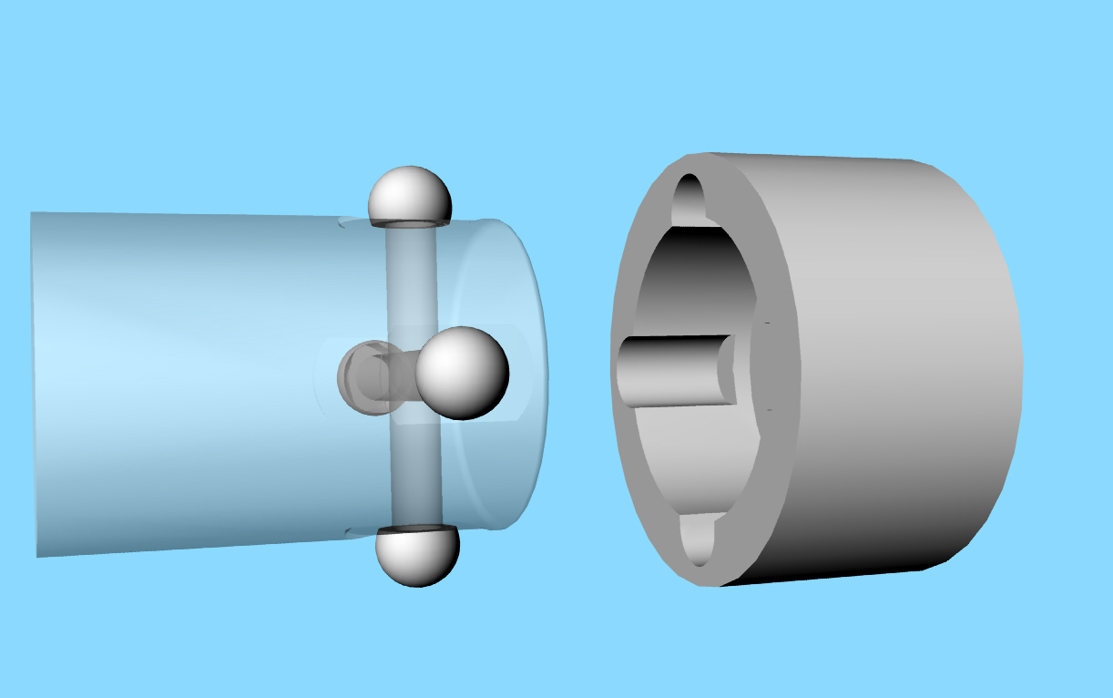
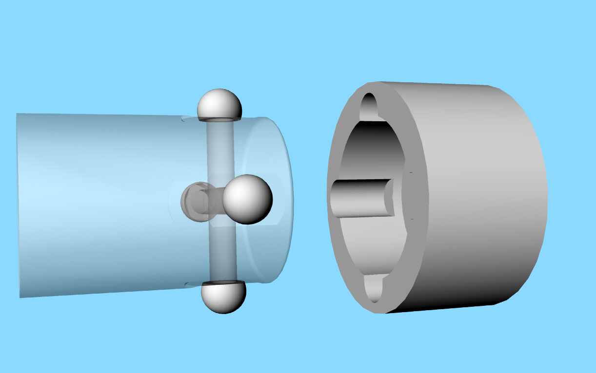
Ok Reeves I rose to the challenge.
This is miniature constant velocity u-joint. The shaft
on the left is 3/8. The balls are off the shelf hardened
and ground ball-bearing balls. The blind holes in the balls and
housing are done with an EDM machine which we have access too.
The balls are then ground flat on one side.
The four 1/8th inch diameter hardened pins are good to 1500
pound each single shear at 125,000 psi. Maybe a bit less due
to the single shear factor. However on a .180 radius that works
out to a surprising 90 foot pounds with four pins.
1/8 inch diameter pin area = (.0625)^2 X Pi = .01227 square inches.
Area X 120,000 psi = 1500 pounds each pin.
Four pins 6000 pounds. .360 dia / 2 = .18 r
Torque in inch pounds is .18" X 6000# = 1000 inch pounds
or 90 foot pounds.
Check my arithmetic please.
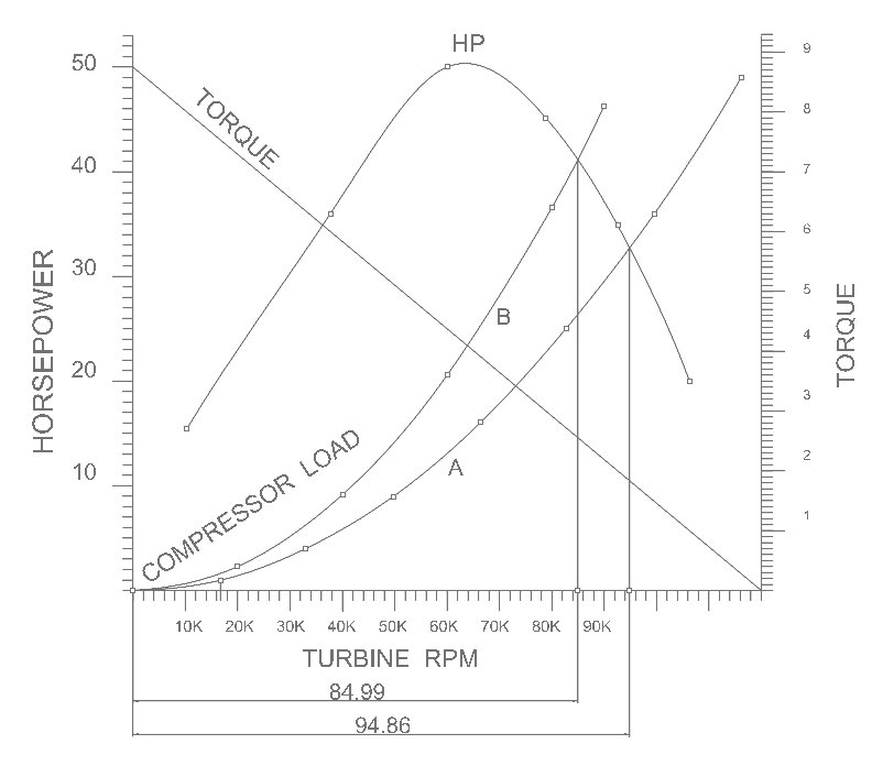
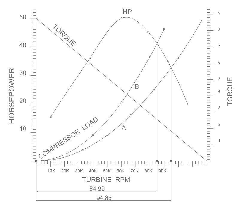
We only need 3 to 5 foot pounds for 50 HP at 60,000 RPM.
The one way clutch does not engage the load until
the gear box output shaft exceeds the RPM of the E-shaft.
This mitigates the high turbine torque at low RPM
I suspect the real limit on wear will be the point contact
of the balls in the hardened housing. Just like any other
CV joint.
This will be plan C if we cannot buy something off the shelf
that works.
Paul Lamar ...No rotor no motor.
The Rotary Engine NewsLetter. Powered by Linux.
ACRE NL web site.
http://www.rotaryeng.net
Copyright 1998-2006 All world wide rights reserved.