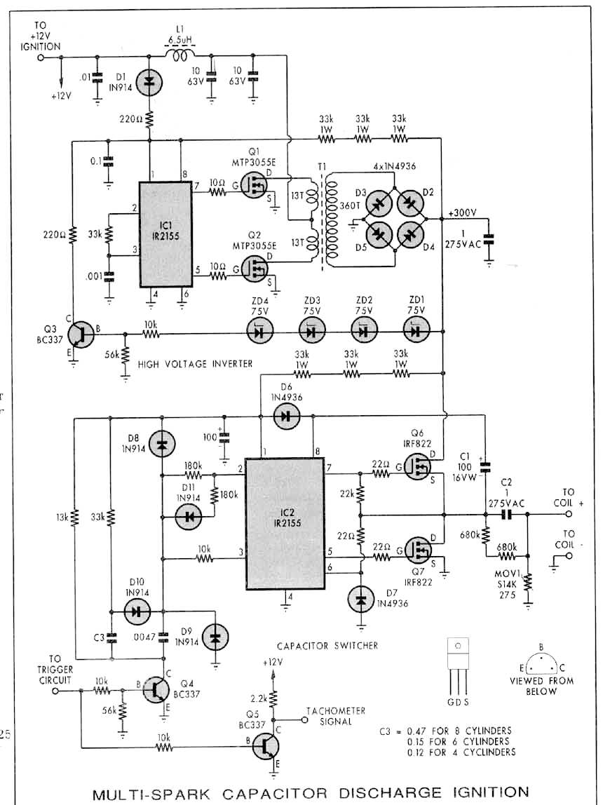
Perry I think you should try an MSD ignition.
Cap discharge
is supposed to punch through lead deposits. Or
build you own.
I think I have one of these I can loan you for
test.
Paul Lamar ...No rotor no motor.
--------------------------------------------------------------
Silicon Chip has a new universal high-energy
electronic
ignition system that
completely supersedes our previous design.
Main Features
Operates from points, reluctor, Hall Effect and
optical triggers,
or 5V signal from engine management computer
5-15V negative earth operation
Selectable dwell period
Coil switches off whenever engine is not
turning
Dwell extension with low battery voltage
Minimum spark duration of 1ms
Two points debounce periods
Special operation for poorly operating points
Anti-theft ignition disable switch option
Optional inverted trigger signal operation
http://www.siliconchip.com.au/cms/A_105632/article.html
This is a subscription based site so it will
cost you $6.70US
to read the entire article.
--Sandy
Perry, here is the one I have. Send me your
address and
I will loan it to you. Keep a set of plugs that
have
been fouled by 100LL and reinstall them for
test on
the ground.
Paul Lamar
----
I'm on a web-based access, hopefully this isn't
an html message.
I haven't burned 100LL for a year, not since my
last trip to KS when
I found out TCP doesn't work. I think it
doesn't work because the
cylinder head temperature is lower in a water
cooled engine. So I
don't have any fouled plugs laying around
anymore. I would have to
install the system and then burn 100LL.
I downloaded some manuals from MSD awhile back
but it wasn't really
clear how that system installed into an RX-7.
Do you think this
system is easily installed and removed?
Send by USPS to PO Box 1553, McMinnville, OR
97128. If you want to
send by other means let me know.
Perry
Ok Perry. There is plenty of data about it on the
Internet.
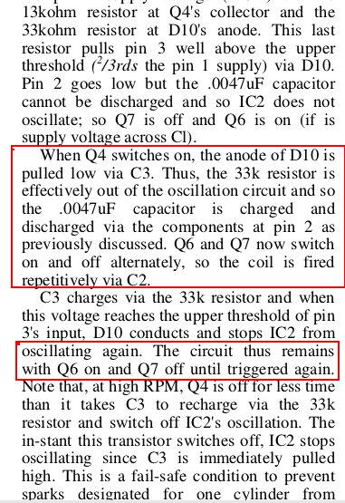
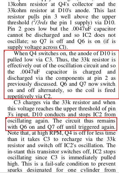
Here is some stuff I extracted from the pdf.
On second thought this is not going to work with the
RX7 ignition system as it fires a single coil twice
per rev and it relies on a distributor to send the
spark
to the right one of four plugs. We don't have
distributors any
more. However this is a very high performance MSD
system.
I think you might need at least four of these
circuits.
They are well worth replicating.
If you want to start from scratch here is an idea
I had a while back.
Shown are three capacitors charged to 300 volts
switching
a coil in sequence by a CPU. Any number of caps and
switches
can be used but the output impedance of the power
supply must
be low and the converter frequency higher than 20Khz
to
recharge the capacitors rapidly. The sequence can be
rapid
or somewhat less than rapid at lower RPMs. In other
words
a variable pulse rate multiple spark capacitor
discharge
ignition system. The limit is the CL time constant.
High C voltage
low L means a rapid voltage rise time with a narrow
pulse width.
The chart from Heinze Heisler s book Advanced Engine
Technology
showing a cap discharge time or pulse width
of 30 milliseconds which is obviously too long for
an MSD system. Perhaps more than 300 volts is needed
for charging the cap. Most cap discharge systems use
a 1 mike cap and 300 to 350 volts. Evidence is if
you go higher
on voltage than this a stock automotive coil may
break down.
I was thinking of experiemtaing with a 15KHz CRT fly
back transformer. 15KHz is a period of .01 ms if my
arithmatic is correct.
7000 RPM is 116.7 rev pere second or 42,000
degrees per
second or one e-shaft degree in .02 ms.
Paul Lamar ...No rotor no motor.ne degree in
The Rotary Engine NewsLetter. Powered by Linux.
ACRE NL web site. http://www.rotaryeng.net
Copyright 1998-2006 All world wide rights reserved.
Paul
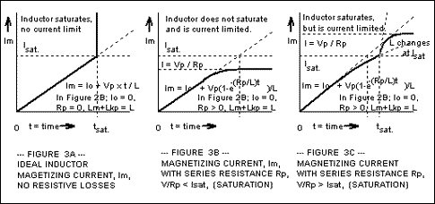
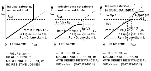
Your fast msd is unlikely to work because the magnetic
core is not being "reset" between cap discharge
events. The core will saturate magnetically with
repeated primary drive pulses of the same polarity.
Same problem is evident in your fires of hell ckt.
Refer to the Clark article previously posted and note
that he addresses the problem with a half-bridge
driver. Time constant generally refers to R X C or L/R
not LC.
Robert
I have never heard the term "reset" applied to a pulse
transformer so I am not sure what you mean.
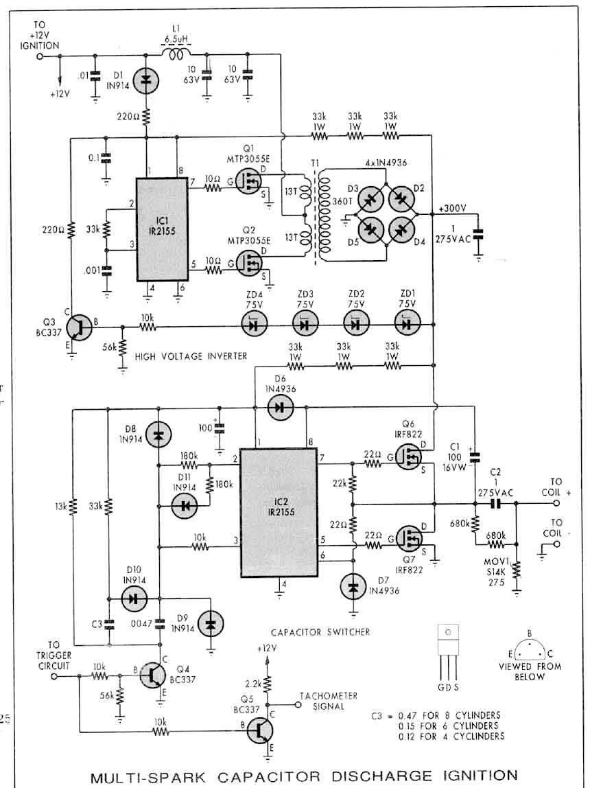
The totem pole circuit Q6/Q7 disconnects the charging
1 mike capacitor C2 from the power supply and Q7 completes the
capacitor/coil series circuit. There is no DC current
through the coil. True LC time constant is incorrect
nomenclature. I was trying to refer to the resonant frequency
of a parallel tuned circuit which is what you have
when Q7 is on.
I show a SPST switch in my schematic
for simplicity reasons but any circuit that does the job
such as a totem pole will work.
By the way there is a typo
in the pdf circuit schematic. Q4 is really Q6,
Note there are two Q4's.
The attached schematic is correct.
---------------------------------------------------------
BTW here is an interesting observation. In an inductive ignition
system the coil is saturated by a DC current. When the current
flow is interpreted by the points opening a high voltage spark is
generated from the secondary winding.
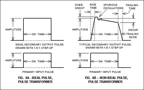
The SAME coil used in a CD system operates in an entirely
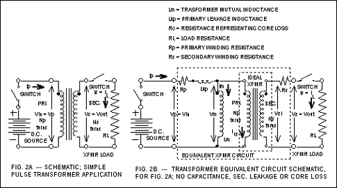
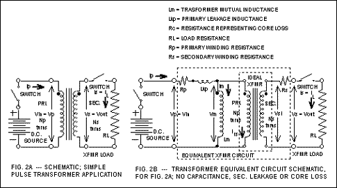
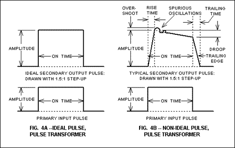
different mode. It becomes a pulse transformer. For more
on pulse transformers see:
http://www.butlerwinding.com/elelectronic-transformer/pulse_transformer/index.html
Note the SPST switches in the pulse tranformer skematics.
However C2 is in the skematic so a DC current is never set up.
Paul Lamar ...No rotor no motor.
The Rotary Engine NewsLetter. Powered by Linux.
ACRE NL web site.
http://www.rotaryeng.net
Copyright 1998-2006 All world wide rights reserved.