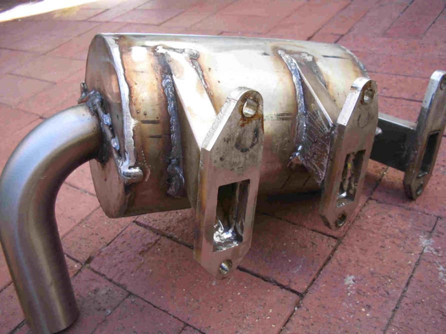
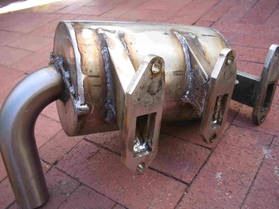
Below is a picture of how Tom Parks did his turbo. No spin that I
know of
but more of a log manifold. Nice Inconel set up. Note how the waste
gate
connects.
For the spin muffler, heater combi I have no idea however of
dimensions of
the inner pipe, baffles and surrounding chamber and thickness of
said parts.
I would appreciate your advice. I have stainless 316 and TIG welder
in hand
waiting to mock up a prototype. Assume a four bolt pattern exhaust port.
Final design after testing would be in Inconel where appropriate.
Thanks
DougFir
Doug,
For the highest energy recovery the manifold should be SHORT period.
That being said, I can see where Tom Parks went with his manifold. The
canister volume should quiet the system some.
I need to interject something for your thoughts. Why would you ever
want to run an exhaust muff (or cool tube) heater? My personal thinking
is that I would NEVER run an exhaust mounted heater if I had a logical
alternative. With a water cooled engine you can easily plumb a
lightweight heater core and 12V fan. You may have discussed your reasons
in an earlier e-mail that I missed. CO poisoning is an insidious killer,
avoid possible exhaust connections to the cockpit if you can.
The intent of the cool tube in my earliest drawings was to draw air in
using the exhaust pulses around an annulus. Mistral's latest efforts
look very much like the VAM design, though they don't bother with a
tangential entry. That makes the muffler easier to make and should
transfer more energy into the center tube. What we were shooting for
was to draw cooler air into the exhaust stream and lower the exit
temperature and quiet the system overall. When they ran the earliest
system at Tracy's they didn't run the tailpipe which ruined the attempt
to pull in air and was too loud. (which I would have expected without
the tailpipe) The area of greatest restriction was removed along with
the tailpipe. I don't think you would benefit much with an internal tube
on the turbo-compound. In inconel 1.5 mm (.06in) is a generous
thickness. With stainless I would run 321 if you can get it. 316 won't
like the high temps as much and will need to be from 2.2 mm (.09in) in
non-direct areas to 4 mm (.120in) in the directly blasted areas and the
exit tubes. The advantage of the thicker stainless is that the exhaust
won't "ring" the manifold as much and it will be quieter, though heavy.
Those thicknesses are for normally aspirated engines: with a heavy turbo
hanging on the manifold thickness will probably need to be 4 mm and
greater. You need to post a hand sketch of what you want the system to
look like then Paul or I might be able to clean it up for you.
Bill Jepson
Bill,
Thanks for the heads up on the exhaust heater. Guess I just assumed that
was the way to go because every plane I have flown takes heat off the hot
exhaust to heat the cabin. CO sensors are cheap and advisable.
I did run some numbers on the hot water heater because in theory it would
work. Ie we have hot water why not use it. Hot water can leak hot exhaust
can leak. Both can be detected.
KISS perhaps dictated my decision on this part of the engine (since
obviously if hasn't on the turbo compounding concept:) but also I ran the
numbers on weight of the heat exchanger, hoses, and blower and wattage
needed to deliver the warm air into the cockpit. A four seater SeaWind
usually has four floor vents and two defroster vents on the dash. The cabin
space is huge. So is a car van though and I know how long it takes to get
the back seat area to warm up on my van in winter. From the engine
compartment down the tail and up to the front window is over 18 feet of
ducting run. The heater core volume, hoses, and blower would have to be
heavier than what is found in a normal auto van mainly because of the
pressure needed to overcome duct resistance. Muffin fans don't cut it.
Rammed air is pretty hard to beat as an efficient delivery system and the
availability of needed defrosting heat is arriving within seconds of engine
start instead of minutes it takes for the water thermostat to open and water
to transfer its heat to air. If my plane had the engine a few feet in front
of me an I had a small cockpit and wasn't planning on flying at 15K+ feet
for 16 hours then perhaps the hot water system would be fine.
For a can type of manifold if there is no attenuation merit in having hot
gases move around a central core than I can leave it out and pick up heat
off of an outer jacket after the turbo. One thing I was worried about with
taking heat out of the central pipe is that I may cool it off too much thus
reducing the energy to the turbo. Supposedly running ethanol already gives
a 75C cooler exhaust as it is.
I hear you on the turbo support point. A lot depends on how the traction
box is connected to it. Mechanically the traction drive can support the
weight of the turbo and I would prefer to have a cooling water chamber
between the two of them. The trickiest design point and another reason why
free moving exhaust pipes won't work is the connection of the traction
drive/ turbine to (in my case) the drive shaft before the PSRU. It will
have to be a robust stable mount and I can't afford to have much expansion
and movement on the hot exhaust side unless it is a predictable linear
outwards movement. I am betting the 5 inch??? pipe manifold will expand in
diameter slightly and perhaps the short rectangular inlet pipes in length
somewhat.
I have a rough Rhino illustration of the whole engine set-up now but give me
a few days to brush it up and add the P. Port intake manifold and
turbo/traction drive mount so I can receive some critique on the different
aspects.
I understand now a central through air tube is not needed. Perhaps some
between what Tom and Ian made.
Thanks for your input.
DougFir
The Rotary Engine NewsLetter. Powered by Linux.
ACRE NL web site.
http://www.rotaryeng.net
Copyright 1998-2006 All world wide rights reserved.