A high speed nose lift; a high speed crow hop; and finally off and away
around the pattern; the 20B powered Velocity, N755V maid its maiden flight
yesterday, 8/04/06. What an exciting milestone – even though in this case I
was watching from the ground as the test pilot did his thing.
The engine performed well, and the pilot reported that all handling
characteristics were good. The flight was short, however; because the oil
temp was 10-15F higher than the limit I had set, and the pilot did the right
thing in abbreviating the flight so that can be evaluated and changes made
as necessary. All in all, with that as the only issue of note at this
point; it was a good day.
It’s such a common thing, isn’t it – these cooling issues. The oil temp
(downstream from the cooler) peaked at 230F, somewhat after the end of the
climb (OAT about 80F); I guess it takes a little while for the hot oil to
get to the bottom of the 8 qt sump and back through the cooler. The main
concern was that the temp didn’t drop more that 3-4 degrees as he went
around the pattern, and after landing and rolling out it was still 225F.
Coolant temps peaked about 190F.
I had a video camera mounted reading the engine monitor display which is
great for review later. Unfortunately, even though I have all sorts of
instrumentation for doing diagnostics, in his focusing on flight
characteristics, and the concern about the high oil temp the pilot forgot to
push the ‘page up’ button; so the only data I have is page 1. Regardless of
further data, it seems clear that there is insufficient air flow through the
wing root oil cooler – a condition that was not entirely unexpected.
Another major step in an on-going process.
Al
---------------------------------
Congratulations Al. You have a very nice airplane there.
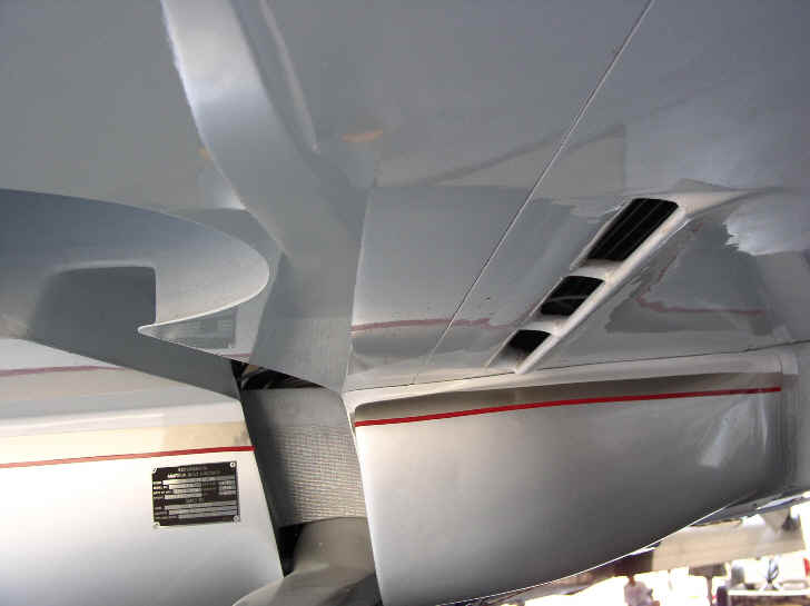
Here are some pictures of Al's oil cooler installation. It is a big mystery
to me why this does not work but this is the second pusher aircraft with this
configuration that has a problem with this. Perry's was the first.
I suspect the boundary layer back there has higher pressure than one
would think. We measured it on Perry's airplane and it was much
higher than I expected.
Time for Me 109 flaps Al :) Perhaps modifying the exit duct as
per red line would help.
BTW Al, I don't have any pictures of the air intake. Can you send me some?
--
Paul Lamar ...No rotor no motor.
-------------------------------------------------
Thanks everyone for the congratulatory messages, and for the
support that is always so helpful. No pics to post yet because
my camera battery went dead after the first three shots,
so Im awaiting for shots from my friend who took hundreds
(OK, only about 150) and will be editing for a while.
The principal issue of the day was the higher than comfortable
oil temperature; most likely due to insufficient air flow through
the cooler. For anyone who would like to think aerodynamics
for awhile and give an opinion on the simplest and best approach
to remedy; read on.
The custom cooler for this 265 hp engine is large. The core
here is about 5 wide, 22 long and 3 1/4 thick. [357 cubic inches.]
It is located in the wing root of the Velocity, behind the spar,
with inlet underneath and exit on the top.
Alan Shaw, who I believe pioneered this
approach, found the location worked very well. When I discussed
the installation with him years ago, he opined that a scoop under
the wing was probably not necessary because of a pressure
differential between bottom and top surfaces. Since then,
my investigations of pressure distributions, and similar
installations that arent working so well, make me wonder.
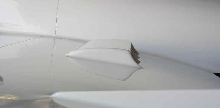
Photo 1 is a view under the wing showing the OC air intake,
wheel well, and the big armpit scoop for the coolant radiator in
the cowl. The inlet opening is about 1 1/8 wide and 23 long.
There really isnt a scoop, just an opening with an extended airfoil
shaped lip which extends about 1/2 into the free stream. The idea was to minimize drag, and assume a more negative pressure
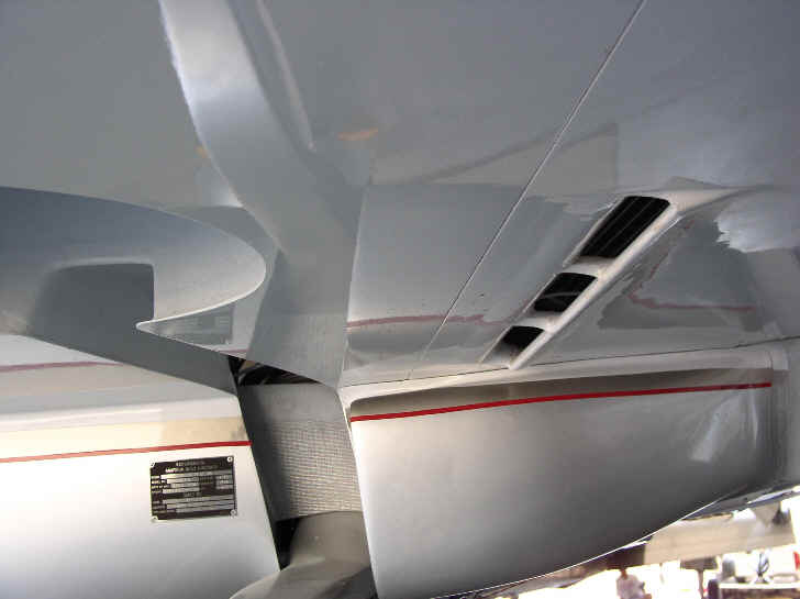
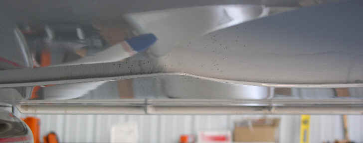
at the exit would produce the necessary flow. Photo 2 shows a front
view where you see the wheel well and the inlet “ very little
extension into the free stream. Analysis suggests that the
turbulent boundary layer on a smooth surface at the inlet location
could be about 5/8“ 3/4 in. thick.
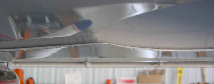
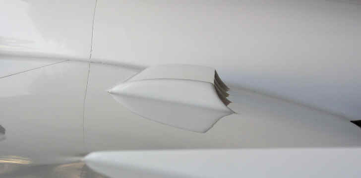
The air exit fairing is shown in photo 3; and is shaped as it is
to maintain attached flow and cause minimal turbulence going aft.
The effective exit area is about 1.6 times the inlet area.
The thickness of the core suggests the need for pretty good
pressure differential for adequate flow.
Here are some options:
a) For the first flight the landing gear was never retracted.
Since the open wheel well forward of the inlet would likely
cause significant turbulence; try another flight with the
gear retracted to see if that improves the results.
b) Place some VGs forward of the inlet to energize the boundary
layer, and see if that helps.
c) Extend the lip of the inlet to form a proper ram scoop,
possible also with VGs forward to break up the boundary layer,
and accept the slight increase in drag.
d) Do something at the exit (local expert suggests there may be
flow separation before the aft end of the fairing causing high
pressure behind the exit). Put VGs on the top of the exit fairing
and/or reduce exit area.
e) None of the above.
I suspect the normal aerodynamic pressure differential between
the inlet and outlet points is minimal; especially in level flight
where it could be near zero. Option c) seems the most sure-fire
to me. Thanks for input.
Al
Did you receive the suggestions I sent Al? They are not
mentioned in your last message just above.
How well is the oil cooler sealed in the duct?
I suspect until you retract the gear you won't know for sure.
I am glad to see that you have eight quarts in the oil system.
Definitely a step in the right direction. My 230 HP O-470
has 12. It takes longer to heat 12 quarts.
The stock second gen RX7 oil cooler core is 19.5 by 4.5 by 2 inches
thick. 175 cubic inches with turbulators inside the tubes.
Does your oil cooler core have turbulators inside the tubes?
Turbulators increase the area and therefore heat transfer from
the oil to the metal in the oil cooler.
Mazda specifies 5 W 30 weight oil for the RX8 engine. Lower
viscosity oil also increases the heat transfer coefficient
of the oil to metal interface. What weight oil are you using?
Is it synthetic?
Paul Lamar
The Rotary Engine NewsLetter. Powered by Linux.
ACRE NL web site.
http://www.rotaryeng.net
Copyright 1998-2006 All world wide rights reserved.