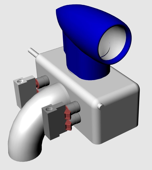
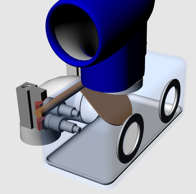
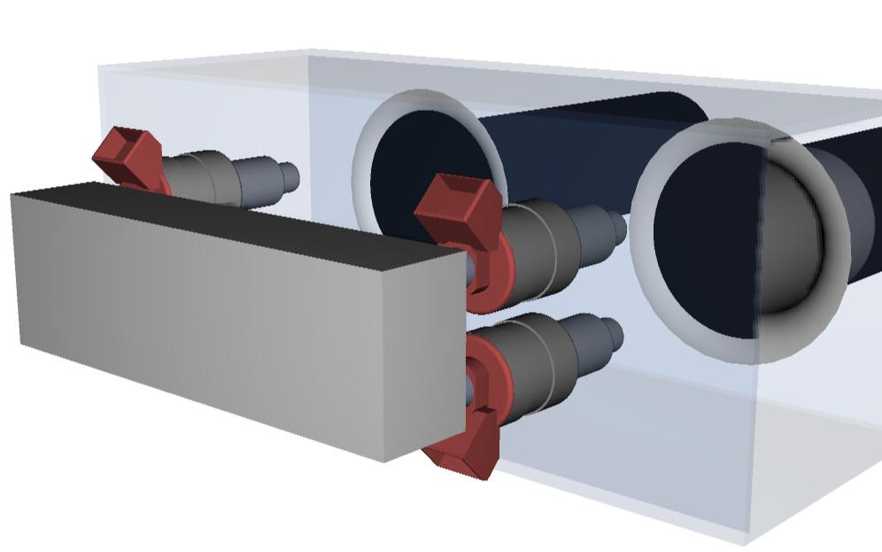
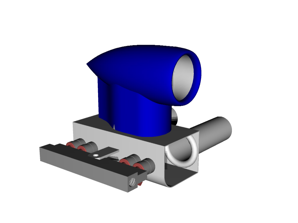
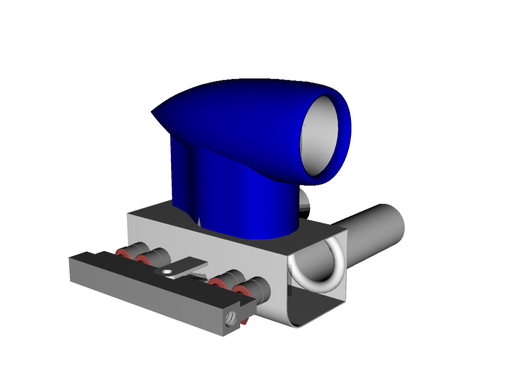
This is the rectangular home made version.
No plasma or laser cutter required.
Nothing you can not do with a modern saber saw, sawsall
or hole cutter. You will need some tig welding for the overall
p-port manifold and slide throttle.
I am sure Ed Klepeis can make the whole thing for you
if you ask.
The Teflon is 3/8" thick and front and rear plates
are 3/16" so the 2 inch runner tubes can be directly tig
welded to them. There will be more drawings and 3D's shortly
Paul Lamar ...No rotor no motor.
Nice job! I like simple things
Joe Berki
Limo EZ
Nice job! I like simple things
Joe Berki
Limo EZ
Thanks Joe. Some metal suppliers like Industrial Metals
Supply in San Fernando in So Cal will shear the blanks for
as little as 50 cent a cut. You will have to cut the holes.
http://www.imsmetals.com/contact/index.htm
I see they branched out to Arizona.
This is the method we use for attaching the 10-32 throttle
cable to the teflon. These are off the shelf 3/8th steel spacers
from McMaster Carr.
http://www.mcmaster.com/
McMaster Carr 3/4 inch OD 3/8th inch long 5/16th ID steel spacer part
number 92415A455 $3.32 well worth it. Page 3001 cat 108
Also buy the precision ground blanks in Teflon. McMaster Carr
part number 9711K2 for 3/8 thick 4 inches wide and 12 inches long.
Expensive but well worth it. +-.005 Page Page 3282
cat 108
Paul Lamar ...No rotor no motor.
More stuff.
Paul Lamar ...No rotor no motor.
Paul,
One point that has concerned me about the slide throttle. At part open
throttle can't air be pulled between the ports via the gap on the front
side of the throttle plate. I imagine the gap is very small. Perhaps a
labyrinth seal could be engraved around the perimeter and top to bottom in
several locations.
DougFir
You can try it if you wish but I'll bet it won't make much
difference. Also an airplane spends 99% of the time at WOT
so any cross tube air leakage percentage will be very low.
All slide throttle have the same proplem.
Take a look at this Jaguar version with the tubes much closer
together.
Something like a TES O ring around each tube might reduce the
leakage. There is plenty of meat in those side plates
to mill O-ring groves. I just worry that the edge of the
hole in the slide will nick the O-rings. I have another
idea that will work better. I'll do a 3D.
--
Paul Lamar ...No rotor no motor.
The drawing shows the fuel injectors mounted between the throttle and the
rotor housings. A previous picture you sent appeared to have the injectors
between the plenum and the slide throttle. Which is better? I understand the
complexity of putting the injectors downstream of the throttle is not
desirable, but what are the trade offs?
Cheers,
Doc
This subject is controversial. Some like them close to the
rotor housings and some like them up stream. Some put them outside
the bells. Out side the bells means you have to deal with all that
fuel vapor floating around. I compromised and put them
between the bells and the rotor housing. Some dyno results
suggest outside the bells gives the best BSFC.
However for car use that is the worst place for throttle response.
Paul Lamar ...No rotor no motor.
The Rotary Engine NewsLetter. Powered by Linux.
ACRE NL web site.
http://www.rotaryeng.net
Copyright 1998-2006 All world wide rights reserved.