Paul and group:
After a little break trying to absorb the hundreds of variables related
to cooling my engine, I've hopefully made a little more progress. I
finally ran out of cardboard making radiator mockups 8-}
A major factor for me is the difficulty vs benefit ratios of different
cooling schemes. Custom vs stock radiators are another. I'm
fascinated by the radiators in the trailing edge flap concept, but this
would have a high difficulty ratio, with wing modifications, 2 custom
coolers, complex plumbing, etc.
It appears that stuffing all the radiators inside the cowling may be
the most workable solution in terms of me actually finishing this
project. Other Goose builders have been reasonable successful with
this approach.
This leaves the following major options:
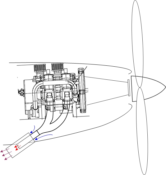
1. One larger right (hot side) water radiator (about 9x14x2), a
smaller left radiator (total >400 cubic inches) with ducting around the
left side to the oil cooler
- see attached crude drawing, which is a TOP view - (please ignore the
residual trash at the bottom of drawing)
- this may work because the smaller left water radiator can allow
enough space for the oil cooler ducting to sneak around the side (need
about 3"x10" area)
- the oil cooler would have to have a bunch of cowl exit slots in the
upper and lower cowling, which are moderately complex, and a potential
obstruction to exit air flow
- plumbing 2 radiators is always an issue.
- this results in a moderately-wide cowling (about 28")
2. 1 oil cooler up front, and a single water radiator on the left
(cool) side, exiting out the cowling (as per Paul's cooling article)
- this results in a very wide cowl (about 32"), due to the corners of a
big radiator and the size of the duct needed to feed it (about 60 sq.
inches area)
- also requires a bunch of cowl exit slots
- the duct would be right up against the spark plugs
3. Two equal sized water radiators up front, and an oil cooler
somewhere else.
- this give a smaller frontal area for the water radiators (using
9.5x11x2 cores)
- this will work using 2" cores, but if some volume could come from a
thicker core (3" evaporators), then even a smaller frontal rofile is
possible
- oil cooler options discussed below
Oil Cooler
A single oil cooler would work on the left side of the engine, with
some difficulty. Another consideration that seems viable is to place
the oil cooler on top of the engine. I can get a 10x11x2" core either
on top of the redrive, or on top of the block, as per the pics. This
could be fed by a separate intake, similar to the implementation
previously posted on the SeaHawker that broke a wing. A long duct from
the very front intake might also work, but would have more resistance
and would have to navigate around obstructions. It would not require a
boundary-layer offset, however.
A top cooler seems to have the advantages of:
- a single, (and off-the-shelf) cooler
- no asymmetry issues
- simple, wedge-shaped ducting
- the exit of the radiator could be open to the air in a low-pressure
area
- small and narrow frontal profile (see pics)
- simple cowling modifications
- note the pictures have a 16" diameter disk at the prop flange,
consistent with Paul's recommendation for cowling exit airflow sizing
(12" prop spinner size not shown)
and disadvantages:
- some complexity of a separate intake duct feeding a wedge diffuser
- the duct intake would have to be elevated up and out of the boundary
layer (1-2"?)
- a front cooler location would have to feed past the alternator (not
shown)
- a location over the redrive would have to duct over Tracy's redrive
plate, and would be closer to the exhaust system
Exhaust
Either of the oil cooler options allows for a side-mounted, 6"
VAM-type muffler, about 8" in length. The factory strongly recommends
the exhaust goes straight up, which would work with a straight pipe or
fishmouth. See the pics of the (very crude) mockups.
The zoomed out view gives an idea of how a side profile of the cowling
might work with a top oil cooler. The front views show where a
top-front or top-rear oil cooler might impact the frontal area.
Hopefully this is progress in the right direction. As always,
comments are greatly appreciated.
Scott Gettings
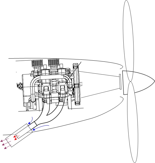
I still say this is your best bet Scott.
It will clean things out from under the cowl.
The fundamental problem is an effective cooling system,
considering the diffuser ducts and scoops, is a high
volume system.
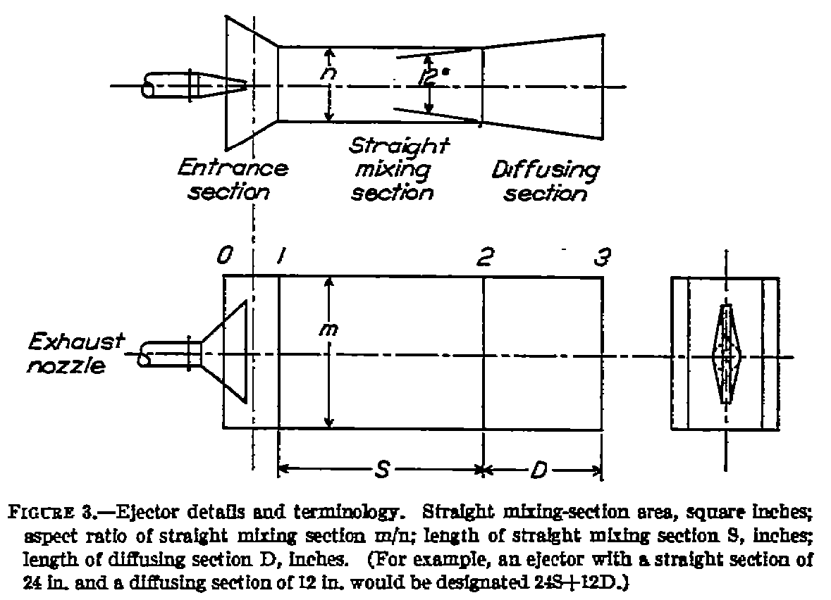
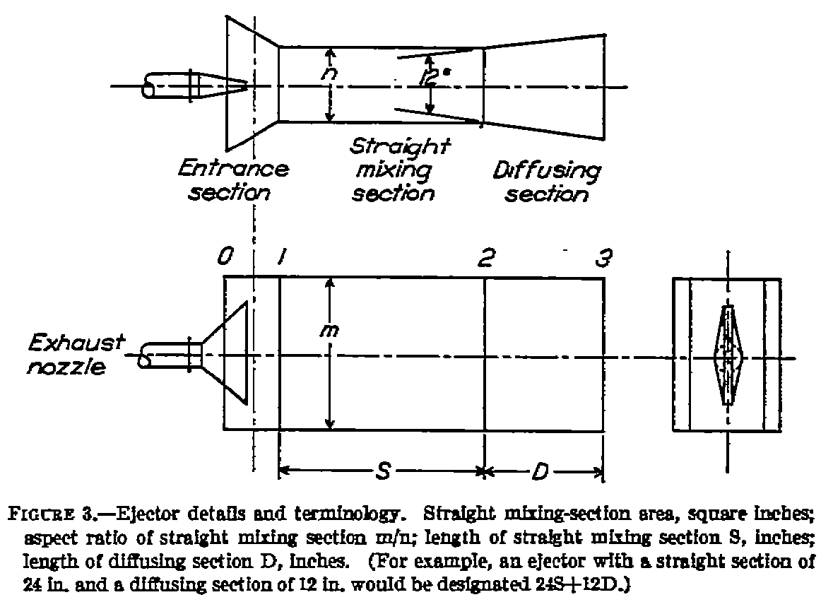
The exhaust ejectors along with the prop will suck air
at takeoff and climb when you need it.
The modern large frontal area thin radiator will work
well at low speeds where you need the cooling.
If necessary there is plenty of room for electric fans.
This is the least technical risk cooling system.
It will work from the get go with no expensive changes.
Paul Lamar ...No rotor no motor.
Thanks as always, Paul. I studied this system extensively after you
originally proposed it, and passed the drawings and various questions
by the factory.
The following make it very difficult to implement:
- the factory is VERY much against doing anything that further disturbs
the already poor airflow coming around the pylon, such as scoops, etc.
This airflow problem is an underlying defect with this plane, which is
marginally compensated by using multiple vortex generators on the side
of the pylon. They specifically advised against big air intakes
hanging out in this area.
- the factory thinks that exhaust heat released inside the pylon is
unsafe, for various reasons.
- the factory has experimented extensively with various exhaust
schemes, and strongly recommends that it only go UP, not through the
prop. A muffler is also a strong plus.
- there is a critical access panel behind the cockpit that would be
blocked by the radiator in that location. This is the only way to
service some control elements in the lower part of the pylon.
- the floor of the engine compartment covers this area, which would
interfere with the radiator in this location.
- the best location for a gas header tank is right under the engine,
against the panel where the radiator is drawn. Otherwise a header has
to go inside the passenger compartment on the floor (or omit the header
tank scheme altogether).
I might be able to duct enough air for just an oil cooler located
farther aft, under the rear bridge, using removable ducting that
allowed access to the control elements. This would be long and
tortuous airflow path, however.
Your suggestions are extremely valuable and highly respected. I'll
look once more at this system, to see if there is any way I might be
able to get it to work, using some compromise between your and the
factory's recommendations.
Scott Gettings
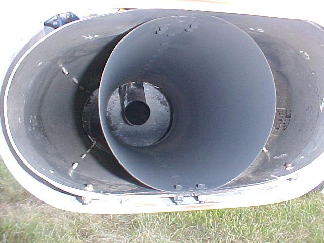
Several composite pusher airplanes have exhaust ejectors and
they use SS sheet to isolate the exhaust heat from the composites.
You can add fiberfrax between the SS and the plastic.
Furthermore the temperature of the exhaust is highly mitigated by
mixing with much much cooler air exiting from the rad.
You will be lucky if the air passing through the rad increases
its temperature over 20 degrees F. On a 100 degree F day the
temp would be 120 degree F. The exhaust gas and rad air
leaving the slot will entrain air from the sides of the cabin
due to the Coanda effect.
"The Coanda Effect has been discovered in 1930 by the Romanian
aerodynamicist Henri-Marie Coanda (1885-1972). He has observed
that a steam of air (or a other fluid) emerging from a nozzle
tends to follow a nearby curved surface, if the curvature of
the surface or angle the surface makes with the stream is not
too sharp."
Air intakes will act like giant vortex generators.
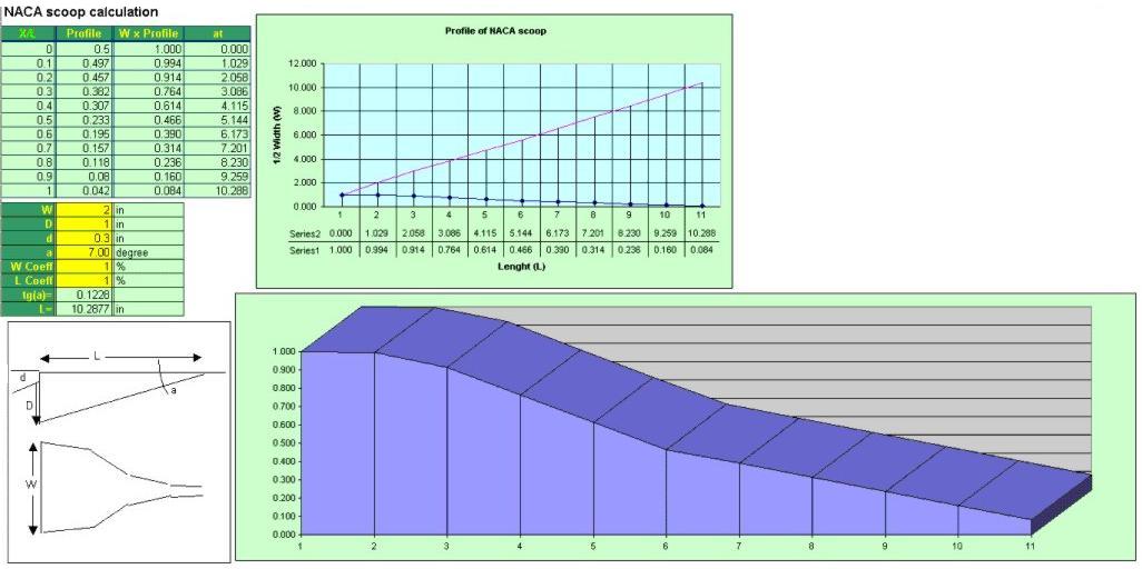
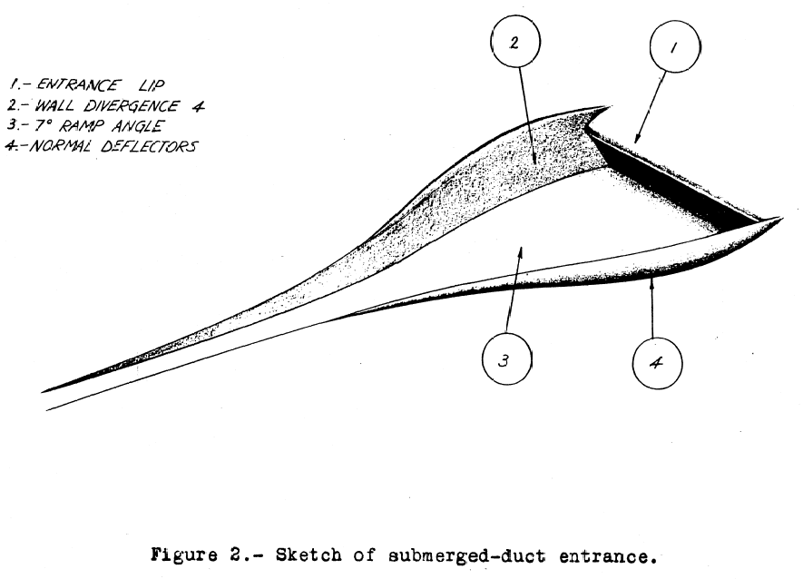
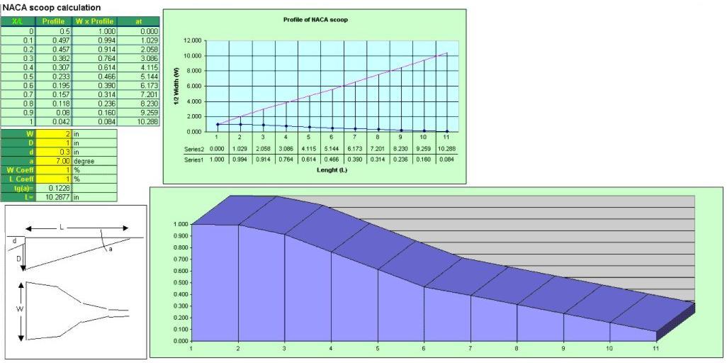
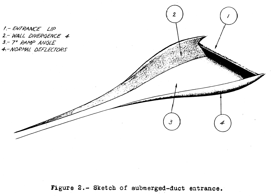
You might try NACA Ducts instead as the air is being sucked out
the back. Use three or four small ones on each side.
Not ideal but that should placate the factory.
Also the reason the factory are have trouble is the slope
of the side of the cabin are too steep. Frankly I suspect the
factory is not up to 1930's aerodynamic theory :)
If you brought the sides out a bit the air would stick better and you
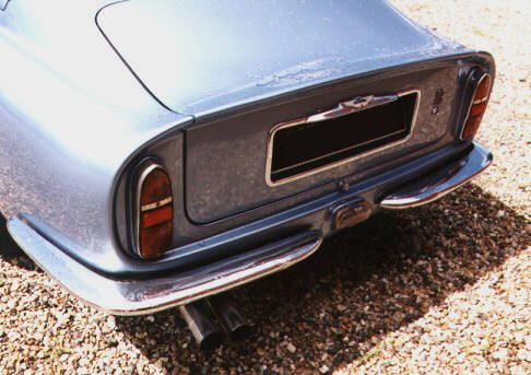
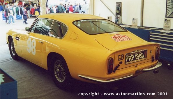
would have what is known as a vertically oriented Kamm tail.
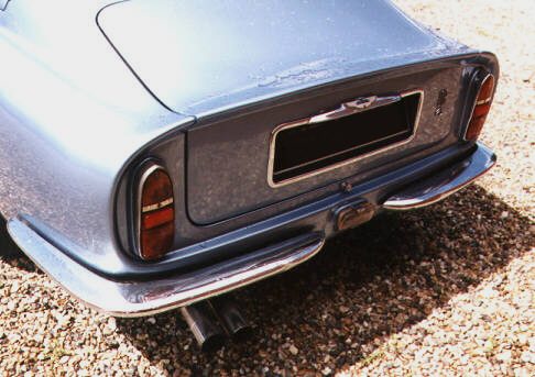
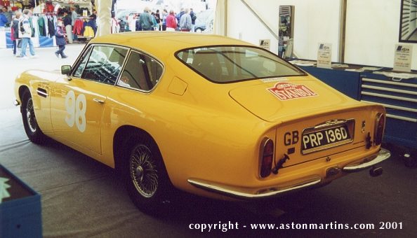
"An aerodynamic type of rear end on a car designed by Wunibald Kamm,
a German aerodynamicist. If memory serves me correctly, it was
originally designed for a late 1930s BMW 328 race car. A bit
hard to describe, so here is are some photo of cars with a Kamm tail."
The thing about them is the pressure on the back panel is very low
so it is an ideal place for an exhaust ejector and rad air opening.
"Kamm showed that a better drag-reducing tail end design for a
car is one that tapers and is then cut off abruptly.
The point at which this must happen, in order for the design to
be a true Kammback, is controversial. A popular definition
is that the cut-off should occur where the cross-sectional
area is approximately 50% of the car's maximum cross-section.
Prior to Kamm's thesis, a teardrop shape that tapered smoothly
to a point was considered optimal. Kamm showed that an abbreviated
teardrop actually worked better; the air still flowed as if the
entire teardrop were still there, but without the surface drag
of the long point.
Usage of the term has fallen off as Kamm's principles have become
more generally accepted."
Various and assorted WWW sources.
Paul Lamar ...No rotor no motor.
The Rotary Engine NewsLetter. Powered by Linux.
ACRE NL web site.
http://www.rotaryeng.net
Copyright 1998-2006 All world wide rights reserved.