>
OK Paul
It might be a few days. Don't forget the pulse
length and voltage. I am not
going to fly again until it is sorted. Local Mazda
say that there has never
been a failure of the igniters. I think the testers
may have tried max and
min voltages testing on my engine.
Non Flying RV7 Ian.
OK here is what it looks like down there.
I'll need a needle scope prob to poke through the
insulation.
I'll give it a try after lunch.
From the RX8 schematic it looks like a FET merely
grounds
the coil when it wants a spark. AKA low side
switching.
To check the avg current will require a major
disassemble
and a jumper so I ain't doing it :)
Jim M, here are the schematics in case you don't
already
have them. Good start on figuring out the RX8 PCM
schematic.
Ian If I were you I would set it up on the bench and
use
an FET to fire it at 3000 PPM (6000 RPM) and measure
the
temp rise. Cars don't run 6000 RPM hour in and hour
out.
--
Paul Lamar ...No rotor no motor.
Paul,
When I was testing ignition coils for MegaSquirt use,
I set up a current sensor in series with the 12V
supply to the coil. Viewing this data allows you to
easily see the current ramp up as the coil charges,
and then hold at some fixed value due to igniter
current limiting. By adjusting pulse width to
minimize the time spent in current-limiting mode, heat
load to the igniter can be minimized.
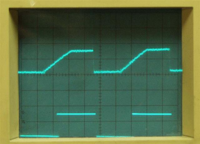
Attached is a pic of the scope screen showing coil
current on the top, and 5v timing pulse from
MegaSquirt below. Note the coil fires as the 5v
signal falls to zero. From my testing minor changes
in dwell setting make a large difference in coilpack
temperature. My testing was done with the 2nd gen
RX-7 ignition components.
To take current measurements, I used a neat chip from
Allegro, called a "current sensor". The chip provides
a 0-5v output signal proportional to current passing
through the measurement side of the chip.
http://www.allegromicro.com/sf/0754/index.asp
I've also attached a pic of that allegro chip mounted
to a little hand-made board for easy attachment to
test circuits. The chip needs only a regulated 5v
supply, and a filtering cap to function properly, so
it's pretty easy to use. Measuring voltage drop
across a very low resistance resistor would work to
measure current as well.
Testing of this sort would allow one to quickly
determine the stock ecu's coil charging scheme, as
well as any current-limiting abilities built into the
igniter. Bench testing could then be performed to
emulate the stock system, or some chosen deviation
from stock.
Roger Enns.
OK Ian I got it. 2.5 ms at 6000 RPM or 3000 PPM.
The voltage was around 11 volts or so as I was not
operating the scope. I was the guy holding the needle
prob inches away from the alternator pulley at
9 or 10K :) took three of us. One in the RX8 on the gas
peddle one holding the scope prob and one operating the scope.
--
Paul Lamar ...No rotor no motor.
The Rotary Engine NewsLetter. Powered by Linux.
ACRE NL web site.
http://www.rotaryeng.net
Copyright 1998-2006 All world wide rights reserved.