Yes it was leaking on the non JB Weld side. Big mistake
using that high temp epoxy I bought. I should have asked
Mazdatrix what they used for p-ports and they would have
told me JB Weld as they did later.
OK it worked great. It is like working on someones teeth however.
You need a small inspection mirror and a small pencil flash light
that will lie in the bottom of the tube. I glued a small
section of 1/4 inch dowel about 3/16 long to a small wood tongue
depressor to apply the small gob of JB Weld to the leaking
area. The vac pump pulled in the JB Weld.
If you want belt and suspenders on
this Burns stainless has 321 SS 1.875" OD tubing with
a .035" wall. Cut the SS tubing just long enough to go
up to where trochoid wear surface starts but not beyond.
Coat it with a very thin layer of JB Weld and insert it into the
aluminum tube. I have some inquires out for even thinner
wall SS tube. On the order of .015" to .020". I think I will
do this with Marks engine.
Best to just pressurize these tubes to 50 psi before you assemble
the engine to check for pin hole leaks.
BTW one advantage of the P-port is you can visually inspect
the trochoid wear surface with a flashlight and a small
inspection
mirror in the compression chamber area.
Paul Lamar
Well, one of my concerns over this approach is definitely
longevity of
the repair. I have no doubt that the current leak is fixed by the
JBWeld sucked into the crack(s). I have more concern over what
will
happen given future heating / cooling cycles.
One of the assumptions we've been operating under is that the first
failure was caused by residual water in the water jacket freezing
over
winter, expanding the tension bolts, & failing one of the
combustion
o-rings. Yet, on tear down we saw no evidence of this -- in fact
I still
have all the original combustion o-rings & they are pristine. I
submit
what actually happened is that the "bad" epoxy was coolant-soaked
during
the dyno runs. This then froze, failing the epoxy in a big way
such
that when I went to refill the engine with coolant, splish-
splash it
ended up in a puddle on the floor.
So - given this scenario I worry about both the heat/cool cycles
from
running the engine, as well as freeze/thaw cycles from the upcoming
winter. Because the existing repair technique can only fix fully
failed
cracks (such that the vacuum can draw in JBWeld) there still seems
to be
a big risk for future failures -- areas where the old epoxy has not
*yet* failed. The scenario above is still very much in play, and
thus I
would expect future failures due to heating / cooling.
I suppose a sleeve inside the existing P Port could in some ways
address
this. But this scenario counts on a very small (and perfect)
ring of
JBWeld holding regardless of the leaks which may or may not develop
behind it. It also counts on the JBWeld to prevent the sleeve from
being ingested into the rotor - not a pretty thought!
Mark
That is a possible scenario.
Not to worry about the sleeve moving Mark. The sleeve is so long
the
epoxy will keep it in place. Also there is no force applied
to the sleeve.
The next thing to do to ease every bodies mind on this subject
it to make a sample. Boil it in anti freeze solution and place it
in the freezer and do it repeatedly.
Many P-port engines have been built over the past 30 years with
different epoxies and different methods of installing the tubes.
I have never heard of a seal failure but then most people don't
store
them in an unheated place with pure water in them either. I think
the guys at Mazdatrix would have mentioned it as well.
Jim and Dave have you ever heard of a leaking or failed P-port?
What ever you want to do Mark. We will take the engine apart and
replace the white epoxy with JB Weld if you wish. I think
the thin SS sleeve is still a good idea as it is easy to do
unlike a press fit.
Paul Lamar ...No rotor no motor.
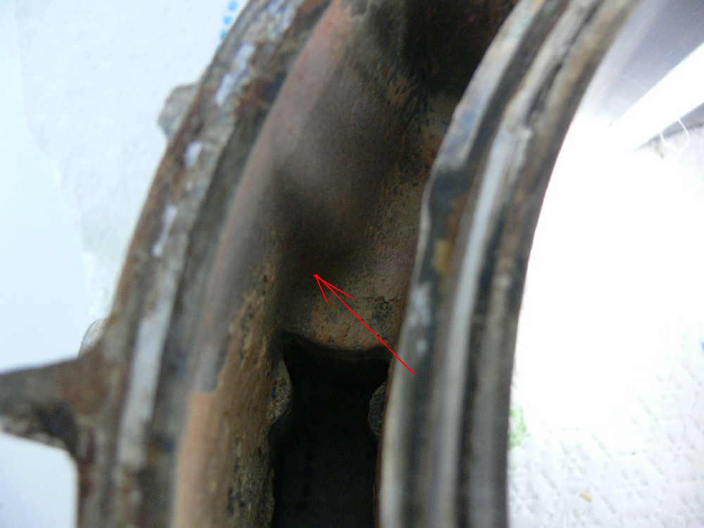
Here is where it was leaking. Gap in the aluminum filled
with the white epoxy. Right where Jerry said it would.
That is why the thin SS sleeve will help greatly.
I can cut it off at an angle to rougly match the
throchoid wear surface contour. It will then be a rather
wide bond area.
Paul Lamar ...No rotor no motor.
Has anyone tried tig welding the tube at both ends to the
housing ? By
pulling the trimed tube out from the housing about 2 or 3 mm and
laying
a very small stitch weld there - only 5 mm or so at a time so the
housing does not get hot beyond the local area. the outside weld
would
not need as much care, maybe 10 mm at a time, Any thoughts ?
-dave
Real risky as the trochoid end is a mix of steel and aluminum.
I think everybody agrees. It is not a strength issue. They
seem to be concerned with the hot coolant effects on the JB Weld
as far as leaks are concerned.
Paul Lamar ...No rotor no motor.
I like the sleeve as a fix. However, I don't think its a model for
future construction. What is objection to just installing the
insert all the way through? Its clean and simple. And, I think,
eliminates all the insert leaking problems. If the slide throttle
flanges could be round, we could build the entire insert at the
lathe, no welding at all. There would be a low stop collar so that
the insert butts up the same depth each time during the fitting,
trimming and gluing phase and a wide collar at the outboard end that
would be the slide throttle flange. That would be a fun project.
Sure there would be $30.00 + worth of chips per insert needing to be
swept but who cares. It would be such a strong, neat looking,
functional part. Jerry
------------------------------------------------------
The sleeve is an additional labyrinth seal. The water has to
turn a couple of corners. If you bore all the way through
you still have a simple leakage path.
Hard to fix too. The thin SS sleeve cost less
than $10 and there is no precision about it. Also there is no
question about epoxy sticking to stainless steel. Way back
in the early 1960's we made composite chassis race cars
with SS reinforcements for bolt holes. We used SS
because epoxy stuck to it better than aluminum.
We also built some bonded aluminum chassis and we either
anodized the parts first or etched them with some sort
of solution I forget which. We were looking for maximum
strength in the bond. I'll research that etching fluid shortly.
This was long before Burt Rutan.
Starting with four inch round and cutting most of the
material off on the lathe leaving a flange is not practical.
You need to weld a flange on the tube. You need the flange
so you can take the engine apart. The original Teflon
slide throttle design can be made by anybody with just hand
tools and a modern saber saw. No lathe required. The hole in
the rotor housing must be done on a mill however I have heard
of people doing it with a hole saw.
--
Paul Lamar ...No rotor no motor.
Jerry,
Yes you explained an identical idea more simply. The whole insert
could also
be turned and bored on the lathe to save the welding step. My
machinist is a
great welder but hates to do it in this situation. Making the
inserts out
of bar stock could be done on a CNC in quantity and be repeatable
and cost
effective.
Paul I hate to say and I mean this in the best interest of the
whole rotary
aircraft engine enthusiasts but doing it over might be the best way.
Other inserts and techniques are just Band-Aids that may bring on
other
unknown side effects. It is not a cost issue. It is a piece of
mind issue.
With more planes flying with P-ports we will find ways of lowering
costs
latter.
All the best
Doug Fir
P-ports like this have been used for 30 years in racing
cars. Racing engines get far more abuse than you will ever
find in an aircraft engine. 11,000 RPM 300 HP and constantly
changing RPM with wide open throttle. Hellish temperatures.
If I did do it over it would be essentially the same. A slip
fit and JB weld. You and others are doing a good job of talking
every body out of p-ports with absolutely no experience what so ever.
It is all speculation on your part. We have a pin hole leak
for @#%$^%&^& sakes. Get back to me when you have actually run
a P-port engine.
Here is what a guy said that actually built and ran a p-port engine.
Richard Sohn
"I can only say the best for JB weld. The inserts on my one rotor
PP have been in there for about 3years with quite a bit of testing,
lots of heat cycles and start and stop. Never had a leak. In addition,
I am using JB-weld on the inside of the WP side housing for building
up barriers between oil and water jackets. Never had one fail so far.
Some of the applications I would not want in a flying engine, however,
only because I would not feel good, not because of observed
insufficiency.
FWIW.
Richard Sohn
N-2071U "
Richard's engine is far more complicated than anything we are
trying to do with two piece end housings no less.
Paul Lamar ...No rotor no motor.
I want to go on record as saying I totally oppose any welding on the
housing. I think it is insane. Secondly, there is nothing I have
seen proposed so far that cannot be done on manual lathes and mills
and with hand tools. No need to worry about CNC. There is nothing
wrong with building things one at a time, measuring accurately, going
slow, LEARNING all the while. There is no evidence what-so-ever
that converting rotary engines is going to be a profitable business.
Forget about that, please. That is not our game. It is irrelevant
that what we are doing is "cost effective" or not. This is a hobby,
a past time, and a passion. It's fun. There is nothing about the
P Port that is exotic or difficult. We are inventing nothing. It
has all been done a thousand times before. That includes gluing in
inserts. Jerry
Right on Jerry.
I just came up with an idea that eliminates the small hole.
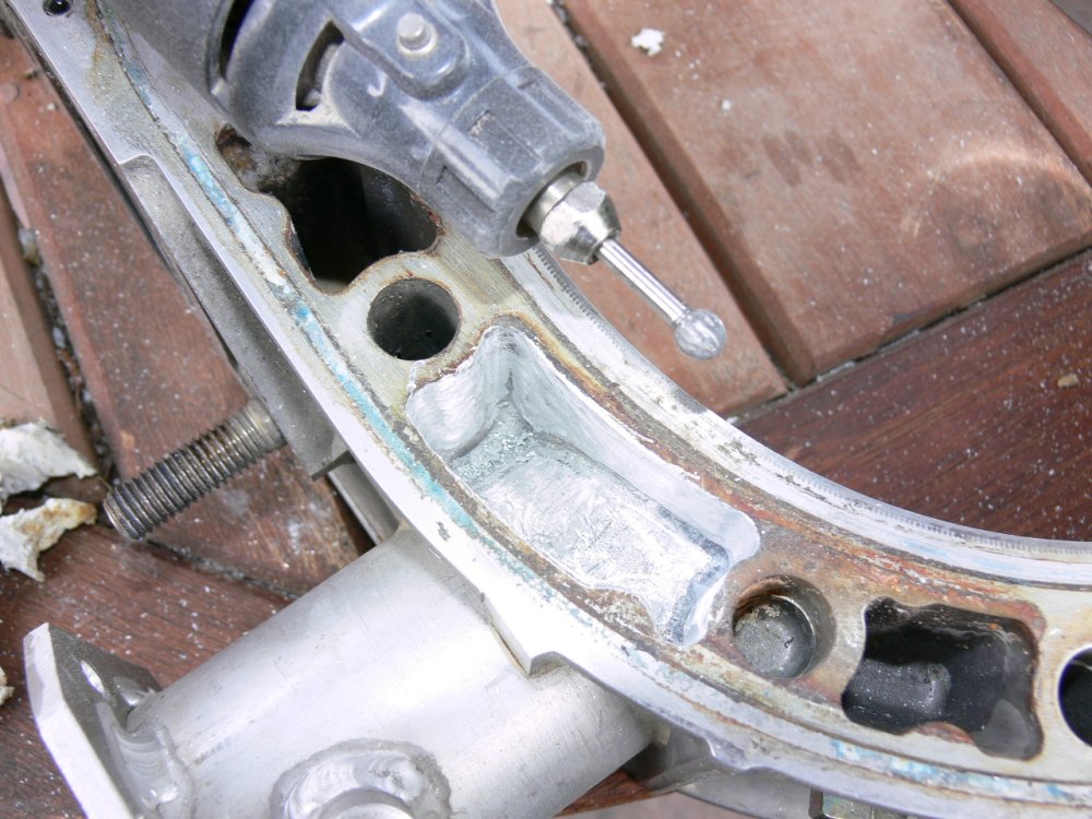
Here are a couple of pictures of the problem area.
This is the other side of the rotor housing from that
side I repotted on Marks engine.
Just clean this area up with a die grinder and hand cut
a chunk of aluminum that just slips in. Bond it in with
JB Weld BEFORE you cut the hole for the tube. Problem solved.
It won't help Marks engine but the Stainless steel sleeve
will do the same thing.
--
Paul Lamar ...No rotor no motor.
The Rotary Engine NewsLetter. Powered by Linux.
ACRE NL web site.
http://www.rotaryeng.net
Copyright 1998-2006 All world wide rights reserved.