None of Tony's polished housing picts came through for me. Could you send
again? BTW I just read about 28 pages of posts about building P-ports on
the RX-7 site along with pictures and comments. I suggest you refer people
to read it as it will save you and them countless hours of speculating about
the what ifs:)
DougFir
------------------------------------------------------------------------------
-------------------
Doug,
Which rx7 site had the p-port info.
Thanks,Geir
This is what I got from Doug. Perhaps you can make sense
of it :)
RX-7 Owners Club - Building Per
--
Paul Lamar ...No rotor no motor.
It appears to be an HTML file.
What I can gather so far... it is about some guy by the name
of Scalliwag that built a P-port with a hole saw on a lathe.
Very clever. It was posted 12-29-2002. I swear I never saw it
before but great minds think alike :) He suggested pressure testing
it.
A lot of the questions we have heard on here were asked then.
Perhaps some of you have read this before :)
The last picture (port27) shows what you are up against with
various other schemes such as O-rings.
Paul Lamar ...No rotor no motor.
Paul
Sorry about that. I saved one of the HTML files and thought that went
through to you.
It takes about 2 hours to read all of the RX-7 post and wade through the
garbage and the gems. Several racers weigh in with opinions on P-port size,
position and grinding techniques and by the time you get to post page 28 you
will notice that almost every epoxy out there is bashed:) That's life. I
hear some people hate tofu also. Lots of good pictures and hints about what
shape the Leman port was.
Start with this link and work your way forward..
<http://www.rx7club.com/showthread.php?t=144200&page=1&pp=15>
BTW the I have done a some drawings using an insert with 1.5mm O-rings
properly slotted in the insert. If the ID is about 48mm and the OD 54mm
then the port can punch through at the same place or open even a little
earlier (if you so desire) at the position Rolf indicated in his Lemans P
timing diagram.
In USA use this size pipe for and angled insert with O rings. But probably
not worth the effort if you do a nice press fit IMHO.
McMaster Carr
4559T611
2" Pipe Sch 80
OD - 2.375"
ID - 1.939"
Wall - .218"
BTW Two seats inner and outer are possible. Outer just. Unfortunately the
insert will be angled up about 12 degrees up from level. May not be a good
thing for air entering the chamber in this manner. Also as Jerry correctly
indicated the manifold would leave the housing about 15mm higher than the
Puerto Rican straight in style and by the time we want to turn it back and
over the engine the bends get severe or the height tall in aluminum. From
the slide throttle it would have to be composite to bend like GURU Racing's
manifold.
Thanks Cary for finding this and for the fine work on your housing. Double
step and deep freeze then light tap or press is what I finally decided on.
Most space saving way. Perhaps a couple of screws to hold it in place as
well. Whew!! Port shape is top secret and I'll let you know when I do. I
notice one reference to a racer named Jesus that potted the housing with
silicon rubber??? Well if it good enough for Jesus its all right by me:)
Doug Fir
I understand you can't get 500 degree F JB Weld in Japan. It must
be on the defense department's top secret not-for-export-list :)
With all due respect Doug you using a sledge hammer where
tweezers will work.
The tolerance on pipe as opposed to tube is all over the lot.
Quoting it to the nearest thou is not the real world.
You will be surprised I am coming around to your way of thinking
in a couple of regards. Press fit is not one of them. Any press fit
requires precision measuring tools and is risky in regard
distorting the rotor housing. I would like to keep this
in the realm of the home builder and keep the cost down.
I am thinking we can machine a .030" shoulder
in the .065 wall tube. What this means is a is 1.940" ID final
hole in the trochoid liner instead of 1.875" ID. .015 material
is machined off the end of the 2 inch OD tube about 3/4 of an
inch long. This should take less than about five minutes on a
lathe. The OD of the end of the tube should then be 1.940".
The wall thickness on the end of the tube .0325 more or less
if my arithmetic is correct.
This is easy to trim with aircraft snips. It is all still a slip
fit. You bore the holes until the tube with the shoulder and flange
welded on but no bolt holes drilled yet just slips in. You use a
machinist level to check the flange orientation. Slip the tube in and
mark around the outside to fit the trochoid surface. Remove
the tube and trim with aircraft snips or any other means.
Sand it all over and smooth it with additional trial fits.
Smear it with JB Weld on the thin end and insert it checking the
position with the machinist level to be sure none of the aluminum
pokes beyond the trochoid surface and the flange is square.
After the JB Weld cures around the thin portion of the tube go
ahead and pot both sides with JB Weld. After that is done assemble
the engine and match drill the flange bolt holes with the back
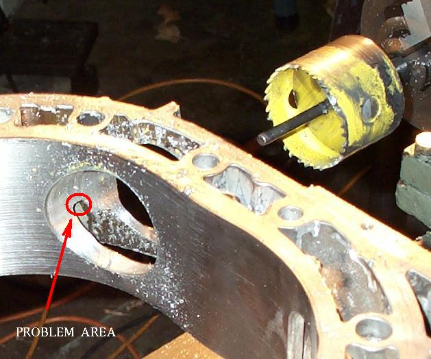
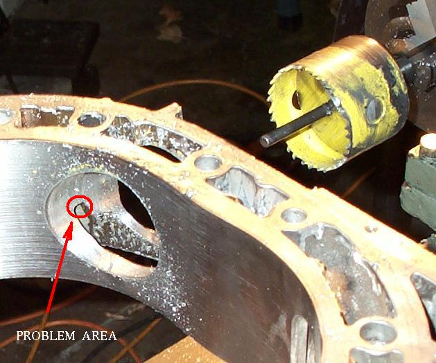
plate of the slide throttle. This blocks the problem
leak area in the rotor housing and by far the cheapest and
easiest way of doing so with the least amount of work.
Here is a shot from the RX7 list of the problem leak area.
With 3000 psi JB Weld holding in the tubes... machine screws
are totally redundant.
Drawings shortly.
BTW Scalliwag's way of using a lathe is ingenious. Many
more people have lathes than have mills. I see no reason
why a boring head can not be chucked in a lathe.
Paul Lamar ...No rotor no motor.
The Rotary Engine NewsLetter. Powered by Linux.
ACRE NL web site.
http://www.rotaryeng.net
Copyright 1998-2006 All world wide rights reserved.