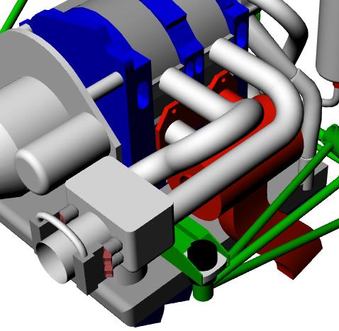
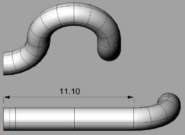
Geir, only because I have already tried "rolling" the pipes can I
say that in this you are wasting your time. The front pipe will
also interfere with the front housing before it can drop enough to
do you any good. If you were to look at my engine you would see
where I have done a lot of grinding to try to clear the pipes. No
luck.
Re: the soft fuel rail. It is so much better for our purposes.
It is the only way to go in my opinion. A real break through. I
suggest you take a look at running the intake tubes to the cowl
nostril on the hot side. Paul did a bunch of drawings on this
about two years ago. I would like to see them again myself
although they did not work for me the first time around. With the
injector problem whipped, this might be a slick solution to routing
the intake.
Paul, can you publish those drawings again. Thanks, Jerry
On Oct 16, 2006, at 11:11 PM, geir2121@netzero.net wrote:
Jerry, You have a point in regard to rolling the aft pipe and a
possable conflict with the h2o pump housing. I'm going to have to
put my engine back together minus the guts to check the fit for
sure. The tubes would only have to be rolled slightly ,just to
create enough vertical clearance for the fuel rail if I were to
use the TWM TB.I have asked TWM for the overall height using a
fuel rail on the TB .
Better yet dont use a fuel rail at all. The weld on bosses we are
trying to use are set up with 1/8 in pipe thread out the
top.Simply roll the injectors enough to clear the p-port tubes
then use flexable SS braided hose to connect your injectors. That
is the beauty of not using a solid fuel rail you can position the
injectors at whatever angle you need.Just a thought.
Geir
---------- Forwarded Message ----------
Gear, about three years ago, I tried to gain cowl clearance over top
of the engine by leaning the intake tubes as you propose. They could
not be leaned very far because of interference with stuff on the end
housings such as the water pump. The actual clearance gained was not
worth the trouble. When you swing them, the first 45º degrees is
mostly horizontal movement not up and down.
If you are going to build composite intake tubes, then perhaps
you can oval them over the engine, transitioning gradually to round
before the TB. If you stick with 2" o.d. or bigger, it is going to
be difficult to squeeze them in. Also, if you end up buying the
sweeps, you will not find them commercially available with less than
3" radius in 2 inch stock. They go down to 2.5 radius in 1.625 o.d.
(1.5 i.d.) I think this is nearly perfect.
Lastly, you have mentioned some intake lengths which seem too long to
me. I have always heard that the ideal intake length would be about
21 inches for 6000 rpm and a little less for 7500 rpm. I feel that
for the intake to be too short is O.K. (we don't care that much about
low rpm efficiency) but to be too long will really hurt performance.
Right when your engine should be coming up on the pipes, it will
flatten out instead. Measure the intake from the inside surface of
the housing to half the length of the bell mouth. Jerry
On Oct 16, 2006, at 3:14 AM, geir2121@netzero.net wrote:
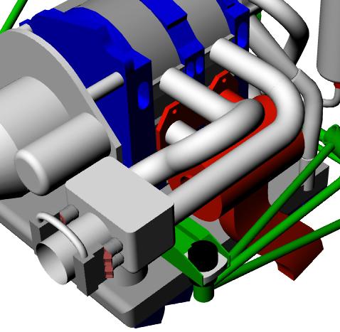
> Jerry, I hope this shows what I was thiking of as far as rolling
> just the intake tube prior to the TB/slide throttle . The aft tube
> would roll towards the firewall and the for ward tube would roll
> towards the prop . If necassary the radius could be increased
> slightly to clear the top of the rotor housings. By rolling the
> tubes you would have enough room above the tubes for fuel
> rails ,injectors , etc. The numbers on the foam start with zero
> beginning at the same vertical plane as the exhaust flange and are
> in 1 inch increments with 25 " being directly above the intake wall
> of the rotor housing liner. I think we could save a couple inches
> by notching the rotor housing to partially imbed the closest
> injector boss,its just epoxy behind the water jacket anyway. Also
> could start the taper from p-port tube to oversized TB in the
> epoxied p-port tube. I allowed 2" for the taper with a seperate
> piece coupled between the TB and the epoxied stub.
>
> Regardless, If you built your own TB there is no doubt in my mind
> this will all fit.
>
> Have a good evening and I'll call you tomorrow, Geir
> <Intake-TB-injector-p-port-tube 012.jpg>
> <Intake-TB-injector-p-port-tube 013.jpg>
> <Intake-TB-injector-p-port-tube 015.jpg>
> <Intake-TB-injector-p-port-tube 014.jpg>
> <Intake-TB-injector-p-port-tube 016.jpg>
> <Intake-TB-injector-p-port-tube 017.jpg>
Well you have me confused. Could you rearranges these
messages in chronological order? I am not sure which
3D's you are referring to Jerry.
Do you guys have a pict of what you are trying to do?
I have not seen the jpg's listed above.
I take it your doing this with mock ups.
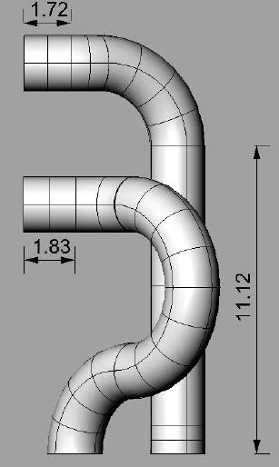
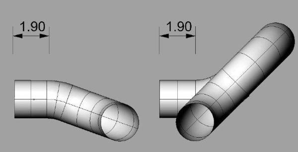
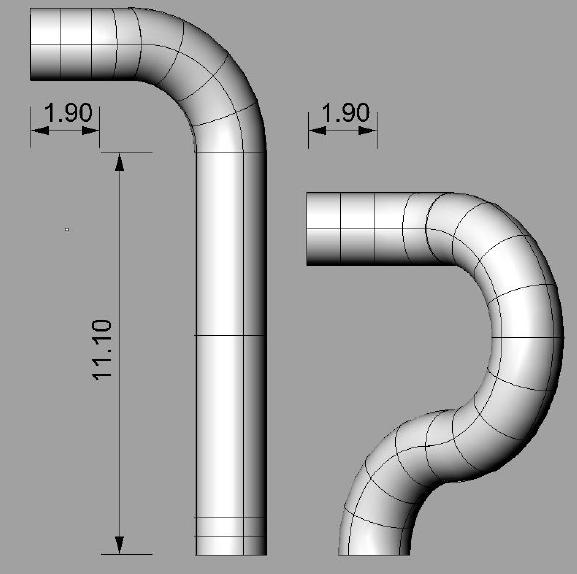
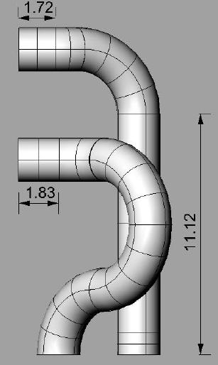
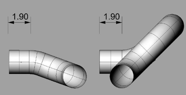
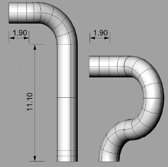
Jerry is very much right about rolling the front tube forward.
Rolling it aft works better. Are you using stock 2 inch tube 180
degree bends with a 3 inch center line bend radii?
Jerry is also very right about making them longer than
about 21 inches. That will kill your HP fast :)
Are you using the stock cowl Geir?
Is this cowl drawing incorrect?-
The angle of the tubes is about right to clear the cowl
drawing shown. Some times you have to grind off a few
minor unneeded parts off the rotor housings.
Paul Lamar ...No rotor no motor.
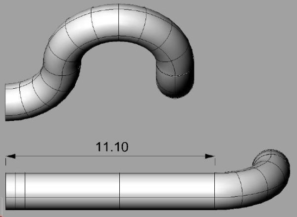
Maybe you should consider something like this.
--
Paul Lamar ...No rotor no motor.
The Rotary Engine NewsLetter. Powered by Linux.
ACRE NL web site.
http://www.rotaryeng.net
Copyright 1998-2006 All world wide rights reserved.