> Hi everyone
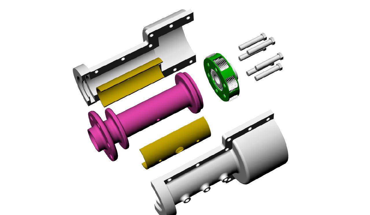
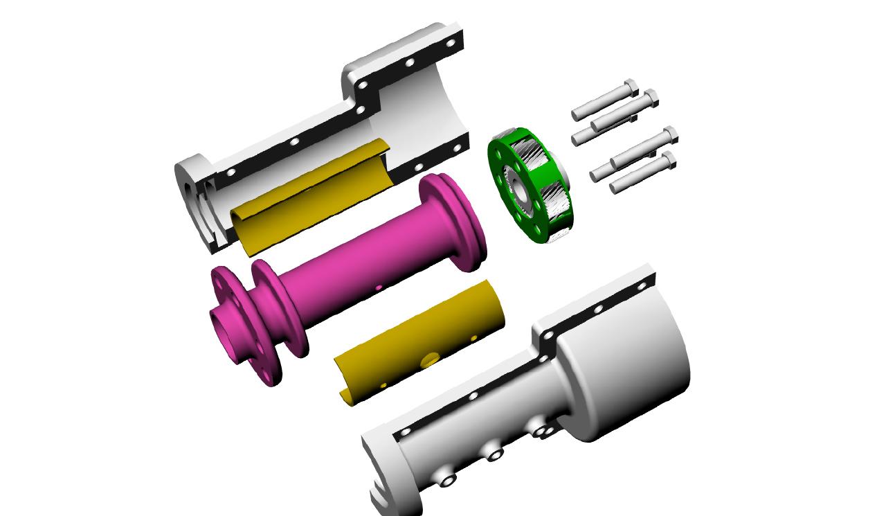
> > > I am now measuring and preparing to draw the Bell 47 housing
parts in Rhino
> so I can share with other individuals. I think before I put it back
together
> I may have some molds of the front magnesium housing and the
intermediate
> aluminum ring made incorporating a few enhancements. I will also want to
> draw up and spec out the other parts in case some of you may want a
similar
> unit in the future. These parts are pricey though. The planetary holder
> appears to be forged and the flange that transfers power from the
planetary
> to the prop shaft was cut from a huge chunk of chrome alloy steel. At
almost
> three inches ID this internal spline flange is way over designed for our
> use.
> > > I also need to purchase a manual so I have an idea on the
tolerances and
> different nomenclature use in identifying the parts. Next I'll need
to seek
> help in identifying the different alloys and heat treatments used.
> > One person that sells Bell parts recommended I should call the
following
> number. Could one of you state side guys call for me? I can't dial a
toll
> free number from Japan obviously. Here is the message I received from
him.
> > Mr. Fir
> You may contact Bell Helicopter Textron (PSE Light) at
> 1-800-363-8023.
> > Ask the individual for the phone # of publications in Texas; you may
> purchase support manuals direct from publications."
> > Good luck with your project.
> > ............
> > My preliminary research has shown that the Bell unit had two back
to back
> planetary gears sets. Both had 3:1 ratios which together translates to a
> 9:1 total reduction.
> > First the specs.
> > *All measurements taken at the gear tooth mid line. Inches are
> approximations.
> > Ring gear 234mm - 9.25"
> Sun gear 120mm - 4.72"
> Planet gear 57mm - 2.25"
> Proof 2 x 57 + 120 = 234
> > Gears are approx. 35mm thick.
> > Planet gears have an internal 5mm boss and their roller bearings are
> approx. 8mm in diameter and 15mm long. They are individually inserted
from
> each side of the gear sort of like loading a revolver with 38 caliber
> blanks. The outer diameter of the inner race OD is about 38mm.
> > > Circumferences:
> Ring 736 mm
> Sun 377 mm
> Planet 179 mm
> Inner race 119 mm
> Gear shaft 57 mm
> Roller bearing 25 mm
> > The PSRU was designed to deliver low speed and transmit the high
torque of a
> large helicopter rotor. It probably was over designed and could handle
> 1000Hp but I have not been able to confirm that claim. Here is what
we do
> know: For each revolution of the final sun gear, each planet gears
rolls 2.1
> times as much. (377/179)
> > > On the Bell 47 unit dual planetary, the maximum rpm output would
be about
> 300. This means the INPUT to the final planetary sun gear was about 900
> rpms. This translates to the planetary gears rolling around their
bearings
> at 2.1 times that speed or 1890 rpms. Not so fast. Now from here on I am
> unclear about what happens in the actual dance within bearings
captivity so
> anyone please feel free to jump in and correct me.
> > They appear to react like little planetary sets. Each roller bearing
> contacts the outer part of the race (within the gear) and the inner 18mm
> shaft at the same time. Well almost. Obviously some clearance is needed.
> Reason would dictate that they are thrown outwards at speed, but then
again
> the whole gear is thrown outwards within the ring gear. Anyway, as the
> outer bearing race is 119mm in circumference, each individual bearing
would
> roll around the outer track about 4.76 times times the gear rotation if
> calculated from the OD. (119/25)
> > If calculated from the ID (the inner gear shaft pin) about 2.25
times (119/
> 57mm)
> > The high number (1890 X 4.76) is about 9,000 rpm. and the low
number is
> about 4,250 rpm. Probably neither number is correct.
> > > The elliptical paths of bearings is academic as we usually we
pick a bearing
> based on the shaft speed, and different loads applied to it and leave
it up
> to the bearing engineers to figure out what is actually going on
inside the
> races. My curiosity has been piqued because I noticed that some of
the used
> bearings had large flat spots on them. Hmmm???? I was told the original
> Bell 47 gear box had trouble with the fiber bearing spacer/holders
because
> they would often deteriorate after 300 hours of use. Dave Garber
eliminated
> them and stuck another bearing in the slot. His clearance between
bearings
> looked minimal if any at all and I wonder if his bearings could
spread out
> enough at higher speed. Dave, has flown his plane a few times to 1000
> feet AGL but how reliable his bearings are is my biggest concern.
Dave is
> determined to seek help in getting his plane prepped for the RENO air
races
> and of course my plane has to be reliable for much longer flights.
> > > When we pump the Bell unit up to the speeds Dave and I will be
using,
> things become interesting. With shaft inputs of 8200 rpms, and using
only
> the larger of the planetary clusters, the prop rpm will max at 2733
rpms for
> take off. The input to the sun gear is still 8200 rpm however and as
such
> and the planetary gears will be spinning on their bearings 2.1 times as
> fast or 17,200 rpm. Ouch!
> > I can just imagine what those large roller bearings logs are doing
at those
> speeds. The phrases 'oil heater' and 'spin weld' come to mind.
> > Obviously I need another bearing and possibly another design
profile for the
> planet gears.
> > Notice I haven't discussed gear line speeds, planetary bearing
loads due to
> centrifugal forces, or oiling and windage yet. That is for another
day. I
> have noticed though that the Bell unit as well as Mistral's PSRU
support the
> prop shaft and planetary cluster via an internal sleeve or bearing
that is
> integral to the e-shaft. That is wise IMHO. Those planetary gears have
> enough work to do without handling prop flywheel permutations as well.
> > About now is the time I am starting to feel all warm and fuzzy
seeing the
> fine work Mistral has done:) But hey I am not bailing just thinking.
> > > DougFir
> > I think it is 2.4:1. As I recall we measured it.
> > You have to put .jpg extensions on those file names
> or browsers will not display them. In fact they are
> not even jpg's. What gives? What kind of camera did you use?
> Where did you get those files? What kind of computer are
> you using? Perhaps you need an American computer instead
> of a Japanese computer :)
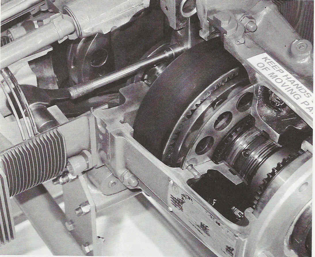
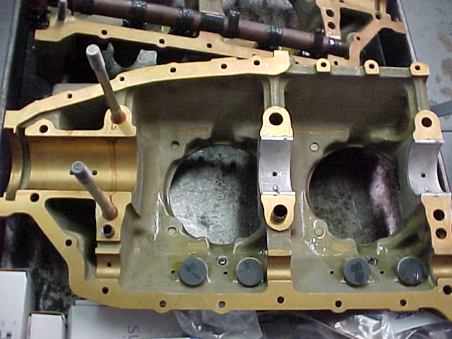
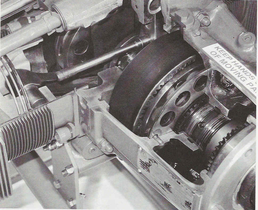
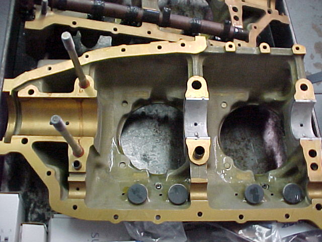
> > OK I have some pictures of the Bell box so here they are.
> > Can you add a hyd constant speed prop feature?
> > Paul Lamar ...No rotor no motor.
Paul
Ok thanks. At 2.4:1 those gears are spinning at 19,680 rpms. Time to
investigate caged roller bearings you mentioned last year although with the
lighter loading a ball bearing might be possible.
My picts were Adobe files created on a MADE IN THE USA (actually Singapore)
Mac. The system soft is Japanese. Can you read this. どですか? I
just
chose the wrong format to save them in. Sorry now falling on rusty sword.
Yes a hydraulic constant speed prop would be possible because I have to
design and construct the prop shaft anyway. For initial engine tests I will
try to make something fairly simple but in the end I think a new front
housing including an additional bearing mount and perhaps an accessory
mount as well would be wise. Tom Parks experience with the Ross gearbox
encouraged me to also plan for a small built-in oil pump, sump, heat
exchanger, temperature sensor, oil filter and metal particle sensor. Any
other things on your wish list? Please don't say 'split case':)
BTW picture # 2 needs some explaining. In our use we take this upper bronze
slip ring off. It has a function with the interface of the primary
planetary. That picture caused me hours of grief last year trying to
figure out how the unit was driven:) The third picture shows it properly
installed only on the bottom.
The slotted drive plate shown in picture #1 is actually one of the plates
off of the primary planetary set sans gears. It now is used as a very
robust sun gear drive mechanism by slipping it over the partially shaved
sun
gear of the secondary planetary system. The shaved sun gear design is
stock. Picture #3 shows it laying on the workbench to the right of the
gearbox. I plan to install six rubber isolators behind this plate ala
Tracy's idea. Dave does not have any isolators in his system and to date he
has not experienced any torsional resonance problems. This doesn't mean
they are not there or won't show up with a lighter carbon fiber prop. His
plane is designed only for short fast flights around racing pylons.
Doug Fir
More pictures I TOOK :) of Doug's box.
How do you plan to do the high pressure oil seal
to the CS hyd prop Doug?
Paul Lamar ...No rotor no motor.
Paul & Doug,
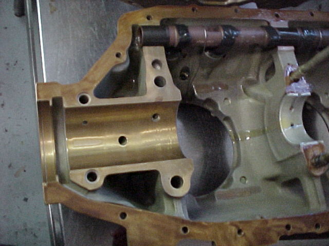
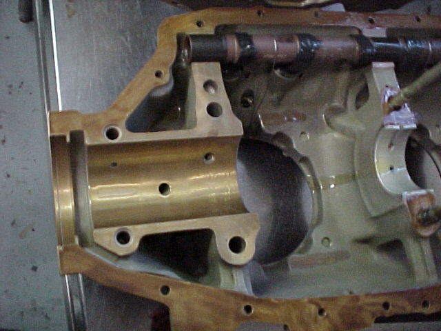
If I might interject, the way several systems are handling the high
pressure connection to the prop shaft is to put a plain bearing surface
on the shaft and compareable inlet holes on the shaft and exterior
bearing. If the housing is wet you don't put seals on it at all, rather
you let the oil exit the plain bearing like all the rest, The volume
won't be high. The typical low pressure end seal and at most an oil
flinger are all that is needed. Marcotte has been doing this on their
system, and I've seen several others in the works. The only thing
against this system is that you must have the room for a 1 to 1-1/2"
wide bearing on the exterior of the shaft. I'm supprised Tracy hasn't
done one. He could extend the front bearing just a little and groove the
exterior bearing with a second feed from the governor. Perhaps there's
no room in the housing.
Bill Jepson
Here are some pictures about what Bill is talking about.
Paul Lamar
The Rotary Engine NewsLetter. Powered by Linux.
ACRE NL web site.
http://www.rotaryeng.net
Copyright 1998-2006 All world wide rights reserved.