>> Paul,
>>
>> What would be the sea level exhaust pressure just before the turbine
>> inlet in a turbocharged engine?
>>
>> I'm guessing maybe 18 psi to account for a little bit of back
>> pressure
>> due to the turbine?
>>
>> Regards,
>>
>> Gordon.
>>
>>
>> I don't have any data on that. I wish I did.
>>
>> Paul Lamar ...No rotor no motor.
>>
> (Snip from my comments October '04... since I never received any
> feedback on these comments, I always assumed no one understood the
> real kernel of turbo wisdom here. This is how 1500 bhp/liter is
> done. So, I'll put it out there again:)
>
> I have seen no mention of this technique in the newsletter, so I
> thought I would contribute some thoughts on turbocharger selection.
> One of the damnable aspects of turbo sizing is trying to come up with
> the best compromise for the dynamics of manifold pressure
> generation: how much, how quickly, how efficiently, and how costly.
> Automotive turbo applications are driven by a much different set of
> goals, primarily their wide-range dynamic response issues. The
> aircraft turbo application is a much happier equation to solve,
> whether it be for all out power, or altitude compensation. In fact,
> there is an opportunity to closely optimize the performance of all
> the components so that some real magic begins to happen.
> It's possible to size a turbocharger so that the engine, and its
> forced induction, as a complete system, operates in 'crossover',
> that is, when intake manifold pressure exceeds the exhaust manifold
> back pressure driving the turbine. The result is a net positive
> scavenge flow through the cycle and the result is significant gains
> in power. Combined with the right intake/ exhaust event timing, BSFC
> benefits as well. This crossover condition can only be achieved in a
> narrow band of operation, but it happens to be the same band that
> aircraft engines are looking for: Part throttle, medium load, and
> medium rpm ( as a % of max rpm)
>
> A program goes something like this:
> Select the 'frame' size, or family of turbocharger so that there is a
> good selection of turbine wheels, turbine houngs, trims and
> compressors available in the range of mass flows necessary. The
> Garrett T04 is such a family. Then, generally on the dyno, the
> turbine side of the turbocharger is selected for its swallowing
> capacity, resulting in larger than normal A/Rs. The objective is to
> use all the gas flow to drive the turbine, not bypass continuously
> through a waste gate. (The waste gate and its sizing still must
> function as a safety/ control device, and for temporary demands for
> higher manifold pressure)
>
> The compressor selection can now be optimized for its output mass
> flow and tailored for its best efficiency. The simplest way to
> verify the component selection is to monitor the exhaust manifold
> pressure just ahead of the turbine inlet, in fact the port can
> sometimes be coincident with the EGT probe location. A small damping
> orifice, around .020 seems to work well, will give steady readings at
> the gage. A similar set up on the intake side, both before and
> after the inter cooler. Then you can go to work mapping the relative
> pressure results vs. a whole range of operating parameters, load,
> speed, temps et al. When you home in on crossover, even if its only
> a .5 psi differential, watch what happens to all the other numbers.
> If you can achieve a 2, 3 or 5 psi lower turbine inlet pressure
> relative to intake manifold pressure, then you've really done a good
> job. You'll see directionally correct moves in the power, temps,
> the bsfc, the ignition timing, et al.
>
> The resulting turbo configuration will be a hybrid: an unusual
> combination of turbine and compressor, most likely much bigger on
> both sides than the automotive application. And operating in speed
> and temperature ranges that are comfortable, safe and unstressed. My
> guess is that none of the stock automotive turbo components will be
> there in the end. The material specs are just not high enough
> ( anyone who flies without an Inconel wheel is asking for it...) The
> power and efficiency numbers will be dramatic, the turbo application
> is truly in its element once this balance has been achieved, and the
> near steady state operation of the IC engine is one of the few times
> we as engine development engineers can come close to this near
> perfect condition.
>
> Reeves Callaway
>
> Thanks Reeves. So re wording this a bit a good system has
> 2 to 5 psi lower exhaust manifold pressure than intake manifold
> pressure. I'll do an example. Lets say we have 10 psi boost
> above atmospheric. Then the exhaust manifold will show
> 5 to 8 psi above atmospheric. Did I get it right?
>
> --
> Paul Lamar ...No rotor no motor.
>
Now we're 'cooking with gas, as it were, Paul. Your example is correct.
And just to emphasize, even the smallest differential between
turbine inlet pressure and compressor outlet pressure is the goal.
( As pilots , we really refer to all pressures in inches of Hg
Absolute. So running 40" of intake manifold pressure using only
39.5" (or less) driving the turbine is the goal.
What scares me most about the turbo discussion on this list are the
signs of impending disaster... tips of turbine wheels eroding, or
gone missing! I can't tell you how wildly over-stressed the
components have to be to do that. In the horsepower and duty cycle
ranges that you are shooting for, the 200-300 hp area, there is no
question that you should all be in the T04b Garrett frame size. I
know nothing about the std Mazda turbo other than it has to be
selected by cost factors, not metallurgy. It certainly was when we
did the turbocharger design/build MazdaSpeed Protege for MNAO
( BTW, we were on the hook for sharing the warranty on those units.
4 years and 6000 vehicles later, I can report that the warranty
incident on the Mazdaspeed/Callaway turbo version was significantly
less than the norm.
In the car biz, a turbo failure is a 'walk home incident'. You know
what it is here...
Reeves Callaway
The standard RX7 Turbo II is about a TO3 size. Other than that we know
little about it. We have had several turbine failures. I suspect
mostly due to over speed. All rather benign without a
total loss of power. I suspect they are running well over 100,000
RPM at 12,000 feet and higher. I have not been able to talk
anybody into installing a turbo tach so far unfortunately.
--
Paul Lamar ...No rotor no motor.
Thanks for that great info, Reeves.
I think most "car guys" are surprised at how big the turbines and
compressors are on aircraft engines. I know of at least one Subaru
guy who fried a turbine wheel in his Van's RV because it was too
small to keep up at altitude.
As you explained, the pressure differential between intake and
exhaust is one of the really key factors that most people aren't
aware of. I was just re-reading an old NACA paper on
turbocompounding from 1944 that really drives this home. As they
lowered the pressure at the turbine outlet -- to simulate higher
altitude -- the power recovered from the turbine increased dramatically.
I'm going to attach a copy but I don't know if its too big to
distribute on the list. The engine is an R-1340 making about 500
horsepower and they hooked up an impulse turbine to the exhaust from
eight of the nine engine cylinders. A separate brake dynamometer was
on the turbine wheel.
At the equivalent of about 30,000 feet altitude the trubine was
making over 100 horsepower, about 21 percent of the engine power
output. This is incredible. One can only guess what could be
possible with a rotary where there is no exhaust valve to eat up
half of the exhaust energy.
Anyway, I got to thinking about why they chose an impulse turbine,
rather than a reaction turbine as commonly seen on turbochargers. Is
it possible that an impulse wheel is more efficient at this rpm and
power? Plus an impulse wheel can be spun a lot more slowly, even 1:1
with engine rpm if the wheel is big enough. (The wheel on the R-1340
was 11 inches and spun about 20,000 rpm.)
I did a quick calculation of turbine pumping specific speed, using a
flow of 300 cfm (for a two-rotor), and an exhuast pressure of 18
psi, and came up with about 1000. This would seem to point to an
impulse turbine as I understand reaction turbines are better in the
100 to 300 range.
However, I also calculated power specific speed which comes out to
about 500 if we assume that we want to make 50 hp with a wheel
spinning at 6500 rpm. It would be higher if we spin the wheel
faster, but I'm trying to see if it could work 1:1. That way you
could just bolt the turbine wheel right to the e-shaft. No worries
about gears or drives -- and nothing to fail. If this can be done
with a wheel of reasonable size, say 12 inches, it could work
nicely. The nice thing about an impulse wheel is that, unlike a
reaction wheel, it is very efficient at low rpm.
The choice of an impulse or reaction wheel for the power recovery
turbine could have significant implications for efficiency. In
turbine engines, there is usually a combination of both, and each is
there for a specific reason. So if there is something to be gained,
it bears investigating.
A company that makes both types for aerospace applications
Barber-Nichols and I will contact them to see what they say:
http://www.barber-nichols.com/products/turbines/axial_impulse_turbines/default.asp
There's a bit of elementary stuff on impulse and reaction turbines
in Wikipedia:
http://en.wikipedia.org/wiki/Turbine )
Regards,
Gordon.
It is too big to publish but I already have it.
Thanks anyway Gordon.
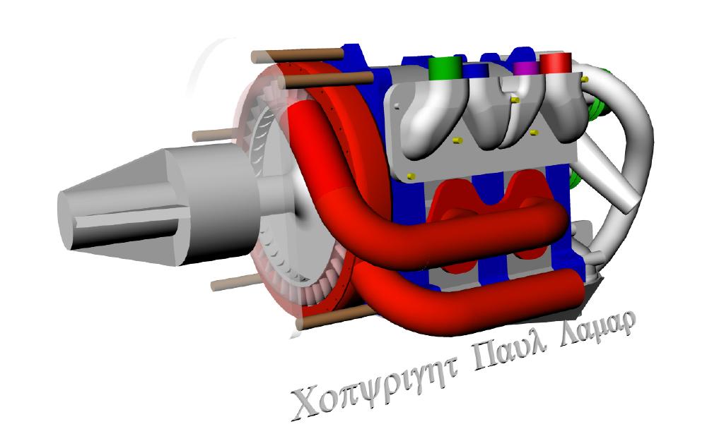
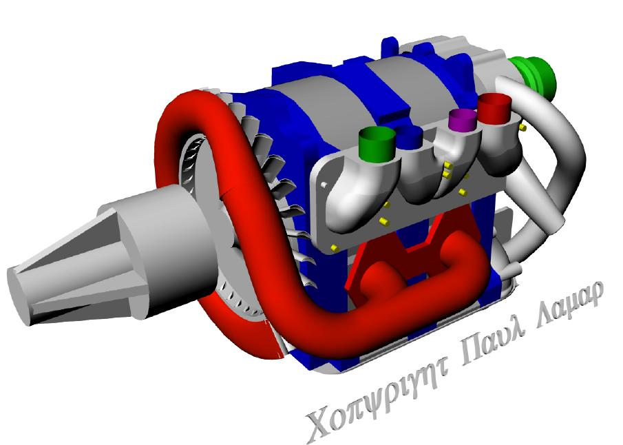
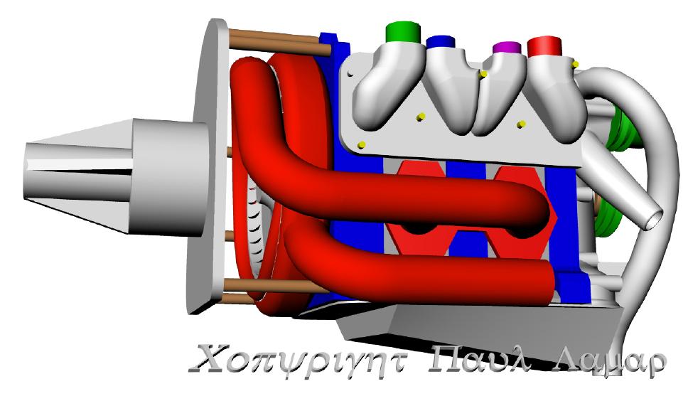
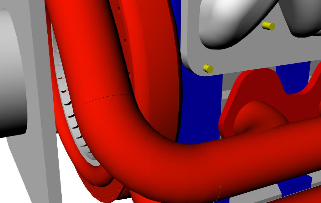
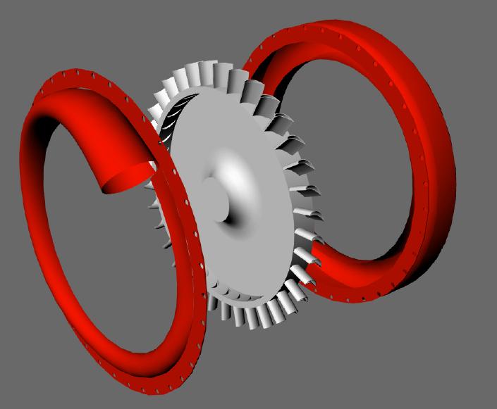
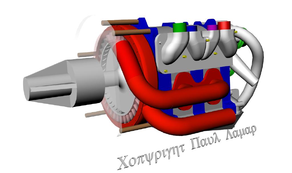
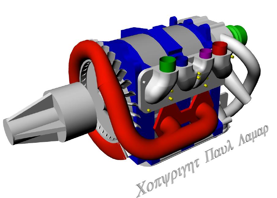
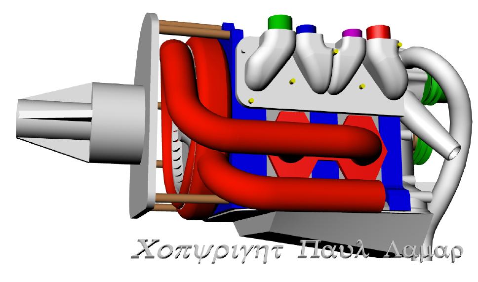
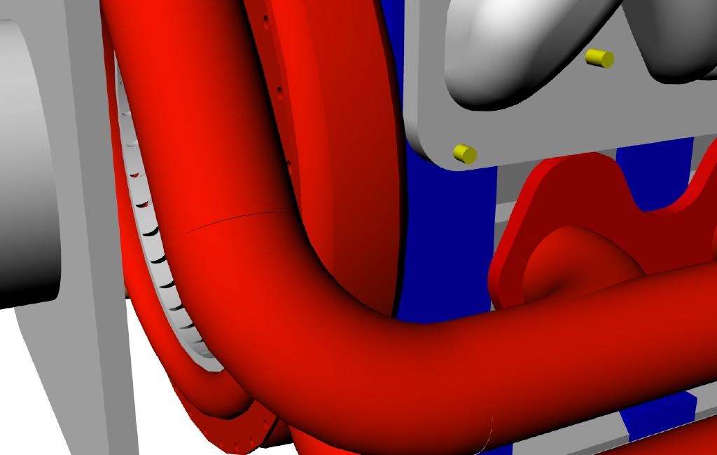
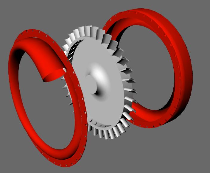
We discussed bolting a turbine to the e-shaft quite awhile
ago. Here are some 3D's. Mark Wrathal did not think too highly
of the idea as I recall :)
Paul Lamar
The Rotary Engine NewsLetter. Powered by Linux.
ACRE NL web site.
http://www.rotaryeng.net
Copyright 1998-2006 All world wide rights reserved.