Doug,
Some questions please!
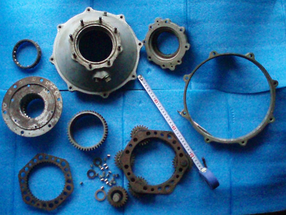
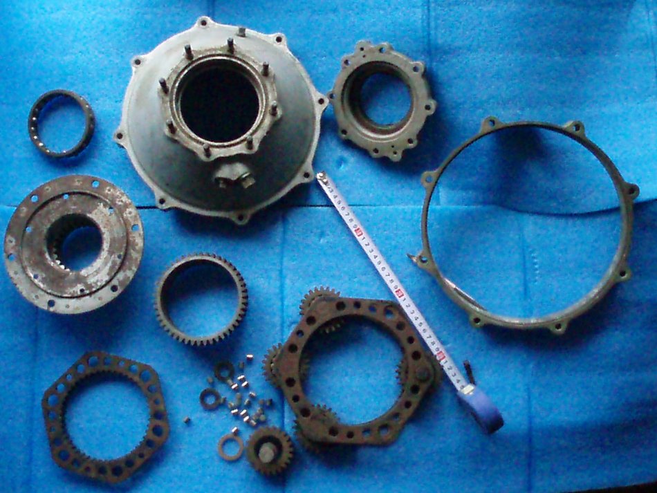
The ring gear seems integral to the Bell Housing is that a press - fit?
The piece to the right of that seems like the seal holder cover plate to the
front of the Bell Housing.
The large ring looks like a spacer ?
Below that is the planetary gears and gear holder.
To the left of that is the sun gear I assume?
The 3 items to the left have me puzzled - what is a cut-off plate, is that
one side of the other planetary gear holder?
The bearing is for ?
The center piece of those 3 items is power in? power out?
Also what is that part that is just showing to the right of the picture?
I have this ratio work sheet for you, if you send me your e-mail address
again!
George ( down under)
[snip]
George
Sorry for the out-of-focus picture. You guessed well. I can send you more of
any part you desire. Right now I'm trying to figure out how to draw a gear
with Rhino. Advise anyone? Make a profile, repeat it in an array around a
circle and then expand the circle into a 3D object?
Ok I'll show how the Bell unit goes together. Look at other pictures that
Paul sent you and you can get a clear idea of how it goes together
1. This is the ring gear. OD of the outer gear part is 254 mm or exactly
10inches. It has a very light press fit. In other words it could be worked
off with a flat screw driver. Integrated onto the ring gear and extending
from the middle of its backbone is an eight 'ear' flange. The flange is
about 6mm tall at its nominal circumference and of course more where it
extends out around the bolt holes. It is about 6mm thick as well. In short
it is pricey piece to duplicate but robust in that the 'ears' hold it from
rotating. Again this is cut from one piece of metal.
2. Magnesium front housing. Its hard to see but at the 11'oclock position
there is an angled hole where oil squirts in on the front bearing.
3. The MRC Aircraft front bearing #9114K inner bearing cage. This bearing
is rusted and is lacking an outer bearing race and the front and rear thrust
plates. In the Bell box this $bearing$ supports the weight of the whole
craft plus keeps the rotor shaft centered. It is inserted from the outside
and held in place with the collar #17 via the nuts on the studs.(See Bell
parts outside picture sent yesterday.)
4. The prop power transfer plate. This unit bolts to the planetary cluster
# 7 and faces the front bearing. It has a center ridge. It is made from one
piece of metal. Not shown is another circular planetary positioning plate
that attaches to the inner part of this prop power transfer plate. The prop
shaft would have a step on the outside and a nut on the inside to lock it to
this plate. The ring of screws around the outside are a mystery to me.
Perhaps some sort of oil slinger or shield was attached.
5. Sun gear inserts into #7 It has a bronze cap on the front edge that
slides on the inside of the prop power transfer plate thus keeping the sun
gear in position
6. Cut off power plate of the initial (primary) planetary set. It is used
as an interface between the engine flex plate and the sun gear. It retains
the sun gear from moving backwards. Lets call it the sun gear drive plate.
See Paul's picture how the sun gear has been 'shaved' to allow this plate
to fit on.
7. The planetary cluster frame and a few of the six planet gears remaining.
8. Roller bearings. 24 of them. 12 per side in Dave Garber's set up.
Less in Bell's
9. Spacer washer between the gear shaft and planetary frame. One on each
side of the gear shaft.
10. Gear shaft
11. Central spacer ring in Dave's configuration is installed on the inner
bearing race and positioned in the middle in line with the gear center rib.
It is the same thickness of the inner rib. It may not be needed as the
bearings don't ride against it. Bell used a weak fiber bearing cage in this
place that held 10 or 11 roller bearings? in place.
12. What I called a collar yesterday. Contrary to what I thought this is
inner bearing race does not turn on the gear shaft. I had to press it out.
13. Planet gear with inner rib.
14. Hmmm what happen to number 14? Lets make it the tape measure. Use to
measure objects in millimeters in the civilized part of the world:)
15. The aluminum spacer housing. Notice the holes and 'ears' line up with
the ring gear and front case 'ears'. This housing gives some clearance
between the sun gear drive plate and the place it attaches to the engine
vibration isolator on my application.
16. The outer oil seal. It is shown inserted into the outer retaining
collar.
17. The retaining collar. This holds the outer thrust ball bearing in
place. The eight "Hail Mary" 1/4 AN studs and nuts hold this collar on. I
pray they continue to do so.
18. Bonus part given to me by an ex Mazda racer cum mechanic when Paul and I
visited him last year. It is a very light weight aluminum flywheel. Unless I
can find a combination lightweight alternator starter of less than sixteen
pounds I will have to use it.
Feel free to ask any other questions.
fir@gol.com
DougFir
The Rotary Engine NewsLetter. Powered by Linux.
ACRE NL web site.
http://www.rotaryeng.net
Copyright 1998-2006 All world wide rights reserved.