Paul,
After looking into it a bit more I have to conclude that the impulse
turbine running at engine speed is not workable. It would have to be
close to three feet in diameter to get good efficiency.
The reason is that the impulse turbine works best at a certain ratio of
exhaust jet speed to wheel speed (about 0.5 or a little below). And
since the exhaust jet is moving pretty fast due to being accelerated by
the nozzles in front of the turbine, the wheel speed has to be fast too
-- just below the speed of sound.
The 11-inch turbine in NACA 786 was spinning at about 20,000 rpm or
about 960 feet per second. The speed of the exhaust jet across the
turbine blades at peak efficiency was 2.5 times that, or 2400 fps.
It should be noted that this is the mean jet velocity, which I assume is
the mean of the velocity of the mass flow and the sonic wave. In the
exhaust manifold, mass flow only moves at about 200 to 400 fps, but the
sonic wave moves at 1500 to 1800 fps. This is actually much higher than
the sea level speed of sound in the atmosphere, but the reason for the
high speed of the sound wave is that it's carried along by the
fast-moving mass-flow. Also the very high temperature increases the
speed of sound.
The attached graph shows how turbine efficiency varies with the ratio of
mean exhaust jet speed to turbine wheel speed. We see that a wheel speed
of less than 0.4 in relation to the speed of the exhaust jet causes
efficiency to fall off.
The exhaust jet in the manifold probably starts out at a mean speed of
about 1000 fps or a little bit less. (let's say 1700 fps for the sound
wave plus 300 fps for the mass flow, divided by 2). But the nozzle jets
accelerate the flow by a factor of about 2.4, to a jet mean velocity of
about 2,400 fps.
This is how an impulse turbine works -- it has a constant pressure
across the turbine wheel, but the nozzles just before the buckets
accelerate the flow, turning pressure head into velocity head. You can
see this pressure versus velocity relationship in the graphic comparing
the impulse turbine to the reaction turbine. The pressure drops as the
velocity increases -- this is in the nozzle, not the turbine wheel.
So if we speed up our mean jet velocity to 2,400 fps, our wheel speed
must be about 40 percent of that for good efficiency, or about 960 fps.
An engine speed of 6,000 rpm equals 100 revolutions per second, so our
wheel circumference must be about 9.6 feet -- about 3 ft.diameter That's
obviously not workable, except maybe for a large radial engine.
Yet another problem with the impulse turbine is that it seems to get
less efficient at altitude as ambient pressure drops. We can see this in
the chart. The reason appears to be the pressure ratio between the inlet
and outlet of the turbine. At high pressure ratios (above 7), the
turbine is less efficient.
This is exactly opposite to what we want. I believe a reaction turbine
should go in the opposite direction, that is become more efficient at
higher pressure ratios, because it works by pressure drop across the
turbine blades. (I could be wrong in my understanding of that).
A third possibility is an axial-flow reaction turbine which would
probably be the most efficient of all, but this is not a common item.
http://www.barber-nichols.com/products/turbines/axial_reaction_turbines/default.asp
You would still need a high wheel speed, even higher than an impulse
turbine (a ratio of 0.7, compared to 0.4), so you would still need a
reduction drive.
So I think the radial-flow reaction turbine (as used on turbochargers)
with a reduction drive is the only workable solution for
turbocompounding the rotary right now.
However, in looking into this I have come across some very interesting
information on producing thrust with the exhaust jet. I will be posting
more on this later, but just a teaser: Would you believe a
maximum increase of 27 percent thrust horsepower? (See attached chart)
This is just by adding the right sze nozzles to the tailpipe and
orienting it straight back. This is incredible and could be key to
making my idea a high-speed rotary-fan engine airplane as efficient as a
prop.
Regards,
Gordon.
Well that is what Mark Wrathal said :)
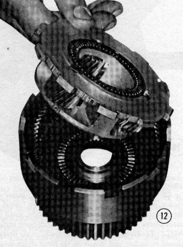
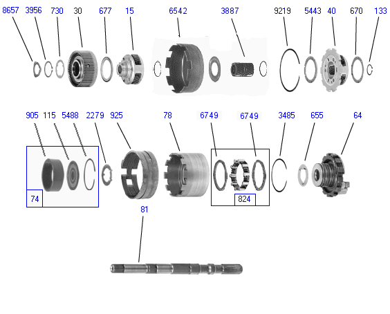
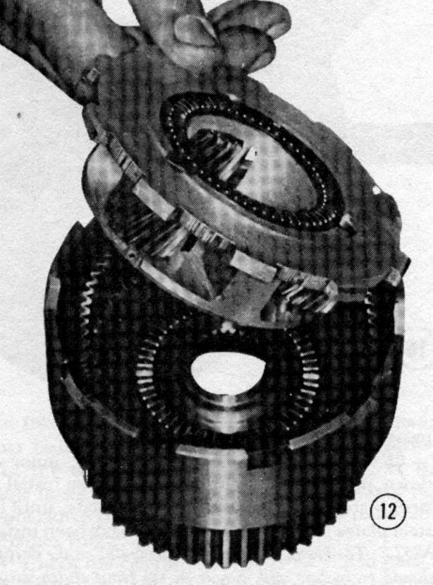
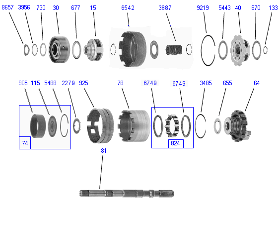
You could always gear it down 3:1 with a planetary.
Would 18,000 RPM work?
Since exhaust thrust is constant it takes a fast airplane to
get significant HP out of it. The exhaust stacks on the P51
were credited with a couple of hundred HP at 400 MPH however top speed
is proportional to the cube root of HP. The cube root of
1400 HP is 11.18 while the cube root of 1600 HP is 11.69
so top speed went up from 400 MPH to 418 MPH or 4.5 %.
Things are not so great down around 250 MPH.
--
Paul Lamar ...No rotor no motor.
Good idea, Paul.
A 3 to 1 gear reduction would be a pice of cake at those modest
turbine speeds -- up to 20,000 rpm. A lot easier than making a
geargbox that can handle 100,000 rpm.
Hmm, maybe I was too quick to dismiss the impulse wheel. Not sure
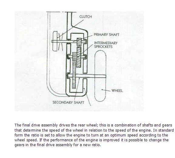
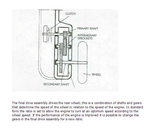
where you could find such a light-duty gear set, but maybe the final
drive of a scooter? Here's one that is a simple spur gear with two
step downs. You would probably only need one to get 3:1 ratio. Then
simply connect it to the e-shaft with a belt and pulleys, which will
easily go to 10,000 rpm.
The whole thing could be done very simply. Of course, you still have
to cobble together a turbine...
Regards,
Gordon.
Jatco in Japan makes a scaled down version of the Ford C6.
Paul Lamar
The Rotary Engine NewsLetter. Powered by Linux.
ACRE NL web site.
http://www.rotaryeng.net
Copyright 1998-2006 All world wide rights reserved.