Paul and Doug,
I just came across a very good way of measuring exhaust pressure and
velocity by way of the CAFE Foundation. About ten years ago they decided
to see hwat's going on in the exhaust of an aircraft engine and how it
might be optimized.
They came up with an idea for an "exhaust pressure graph," an
instrumentation suite that they then hooked up to a Lycoming in a
Mooney. They tested various exhaust systems and even thrust nozzles and
presented their findings in a series of articles.
You can download these articles from their website, they are the "EPG"
series:
http://cafefoundation.org/v2/research_reports.php
Their method was very simple but thorough and did not seem to involve
any epxensive instruments. They used what appear to be ordinary pressure
transducers that produce a voltage signal. They cutom made some
electronics to amplify and digitize the sensor voltage and then brought
the data it into a software program to log the data, graph it an analyze it.
They used "sampling ports" on the exhaust pipes which I think are just
holes with little bosses welded to them. They attached 1/8' diameter
copper tubing 18' long to these ports and then used soft silicone fuel
hose to connect the pressure transducer to the copper tubing. So no need
to worry about high-temperature pressure sensors, the sensors are far
enough away from the heat source.
The first sensor is placed about an inch aft of the port and another
sensor is placed a couple of feet downstream -- they could then easily
register the speed of the pressure wave by measuring how long it took to
get from one sensor to the other.
They used a magnetic crank trigger to record the position of the
crankshaft, pistons and valves in relation to the exhaust pressure pulses.
They pulled some very accurate data using this setup and this could be
fantastic for doing a detailed analysis of exactly what's going on in
the rotary exhaust. I would say this is a must for optimizing a
turbocompound configuration -- even a turbocharged engine. It could even
be useful just for optimizing the exhaust on a normally aspirated engine.
The whole thing doesn't sound very involved or expensive. A simple
circuit could be devised for digitizing the sensor signals and you could
just pass the data into Excel for logging and analysis.
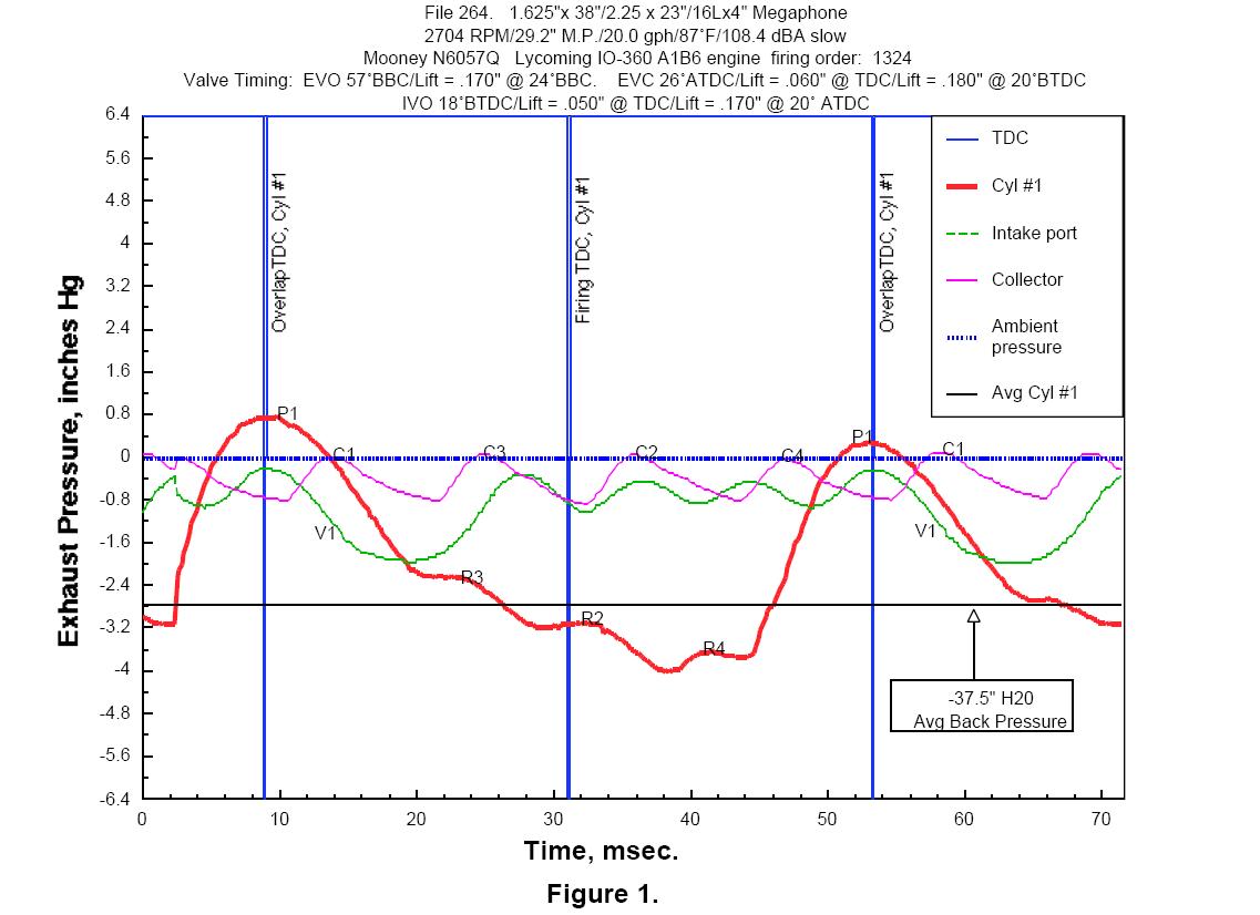
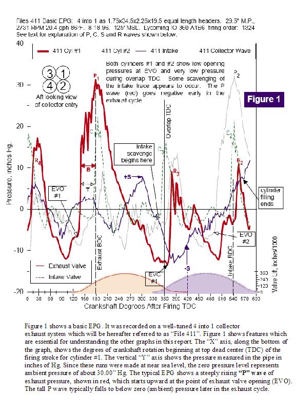
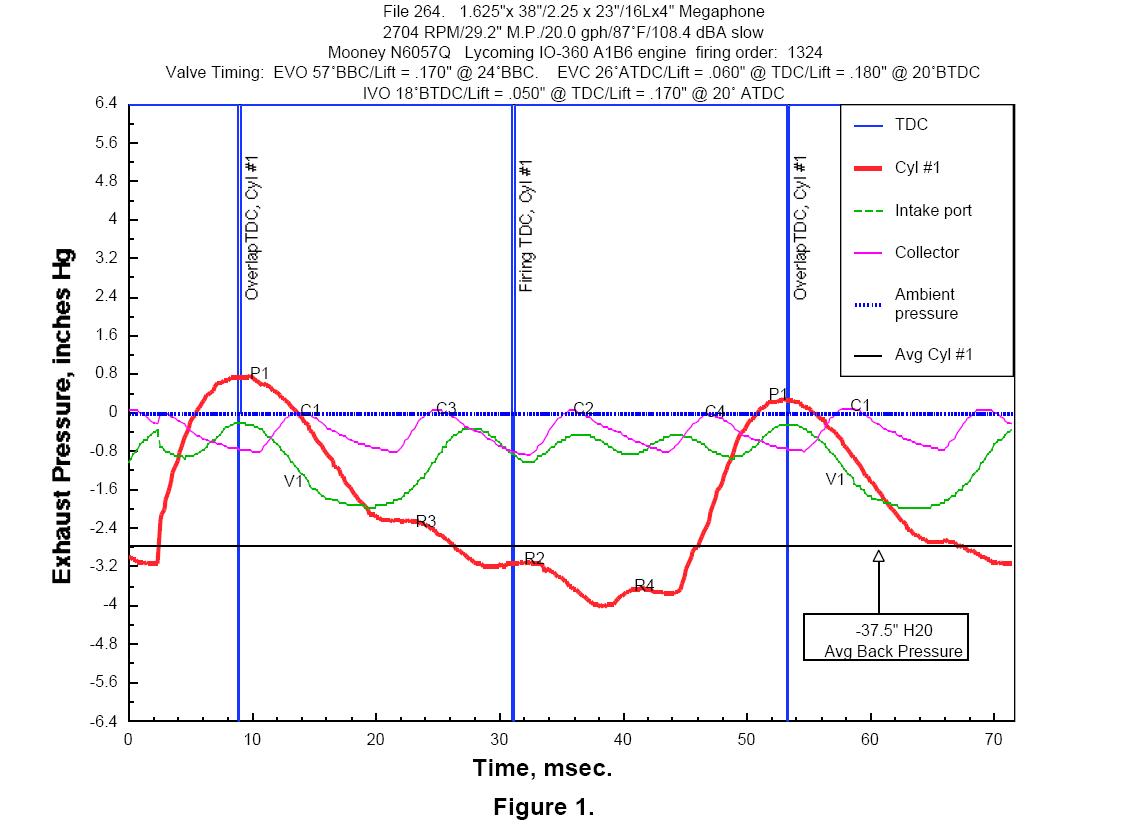
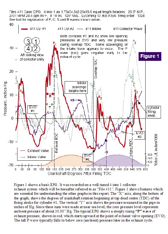
I've attached a couple of the graphs they came up with. The red line in
Figure 1 is the continuous variation of the instantaneous exhaust
pressure. The wave tops are the pressure peaks as the pressure wave adn
reflected waves travel down the pipe. "P" is the pressure wave and "R"
are the reflected waves.
The second graph shows more detail.
The whole series of articles is very fact-filled and informative.
Regards,
Gordon.
The Rotary Engine NewsLetter. Powered by Linux.
ACRE NL web site.
http://www.rotaryeng.net
Copyright 1998-2006 All world wide rights reserved.