>>>> BTW a good example of a Helmholtz resonator is blowing
>>>> across the opening of a Coke bottle.
>>>> Paul Lamar
>>>
>>> I suspect if you apply the Helmholtz resonator principle to an intake
>>> manifold properly you may reduce the length of intake pipe necessary
>>> to tune the engine. Since the length required is shorter the
>>> internal skin friction drag is also less. At least I think this
>>> is what Porsche is up to. I could be totally wrong.
>>>
http://www.phys.unsw.edu.au/~jw/Helmholtz.html
>>
>>
>> Hi Paul,
>> are you suggesting using the resonator as a pressure accumulator,
>> analogous to a capacitor in a tuned radio circuit?
>> Must it be mounted with the inlet 90 deg to the airflow?
>> It follows from your graphs showing tuned length as related to varying
>> diameter of inlet tract. Or, we could mount one on the end of a plenum
>> to resonate with all the inlet pulses, like a sophisticated air spring
>> that resonates with the inlet pulses; like a vibrator
>> Perhaps I am describing two different implements here, one a capacitor,
>> and the other the H resonator. I imagine each inlet would have to have
>> its own H resonator, set at 90 deg to the flow.
>> If we could shorten the inlet tract, this could be a useful gadget.
>> BR, Dave McC
>>
>> I would need a Phd in acoustics to begin to know how
>> to apply the principle. I don't have the foggiest :)
>>
>> Maybe with a $1,000,000 budget, a dyno and five years I might
>> be able to come up with something :)
>>
>> Paul Lamar ...No rotor no motor.
>>
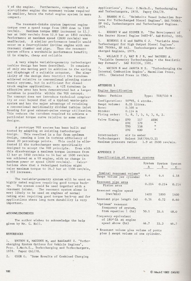
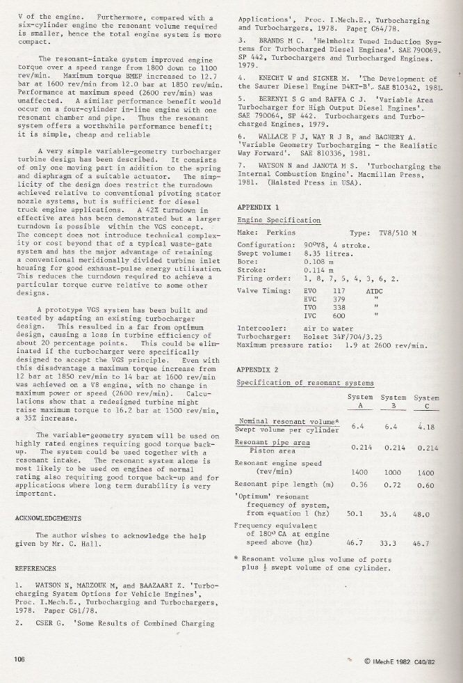
>> I was looking through a collection of technical papers on turbocharger
>> looking for back pressure data that Gordon was interested in.
>> I came across these papers that deal with Helmholtz resonator
>> intake manifold design in piston engines. As Dave M says we could
>> shorten the tubes if we had the right volume of chamber on the end
>> of them. This is a light at the end of a tunnel.
>>
>> That would solve a lot of installation problems with
>> low cowls.
>>
>>
>> Paul Lamar ...No rotor no motor.
>
> Dave Mc and Paul,
> Perhaps a resonator (set at 90 degrees) with a variable length, to tune for
> best results would be a good idea. Wouldn't have a clue as to diameter
> though - any indications from past photo's. May need to be restricted to the
> diameter of the intake pipe?
> George (down under)
>
Well, I should probably not say anything, but I kinda sorta recall
from a long time ago, from a class I wasn't very interested in, that
the frequency of vibration of a resonant column of air depends
primarily on the length of the column and the speed of sound. There is
an optimum ratio of the length to the diameter of the pipe for a given
purpose. Think of a tuba, a trombone, and a trumpet. Another good
example is a pipe organ. As you change the ratio the quality of the
sound changes. This is because of secondary and harmonic vibrations.
What does this mean for engine induction? I don't know for sure.
Probably it means there is no free lunch.
Doc Custer
Retired software engineer and sometime Audiologist
Building RV9-A. Fuselage
I don't know about free lunches but organ pipe tuned
induction systems certainly work.
---------------------------------------
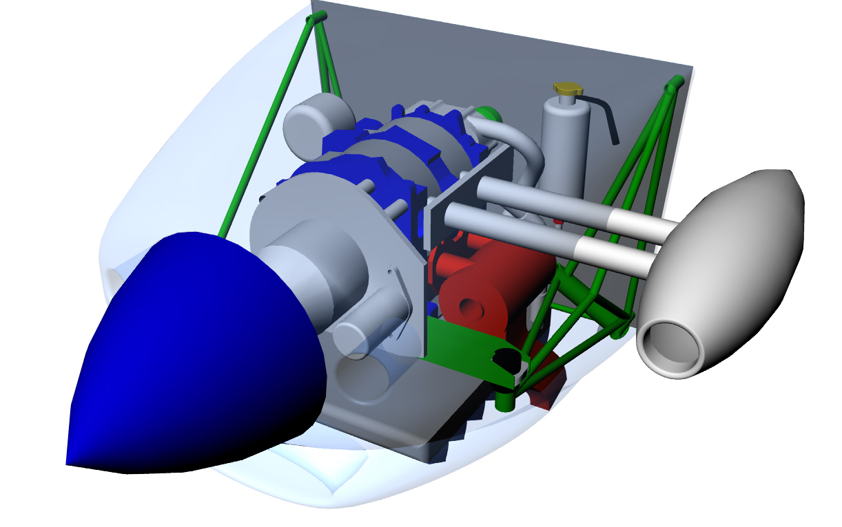
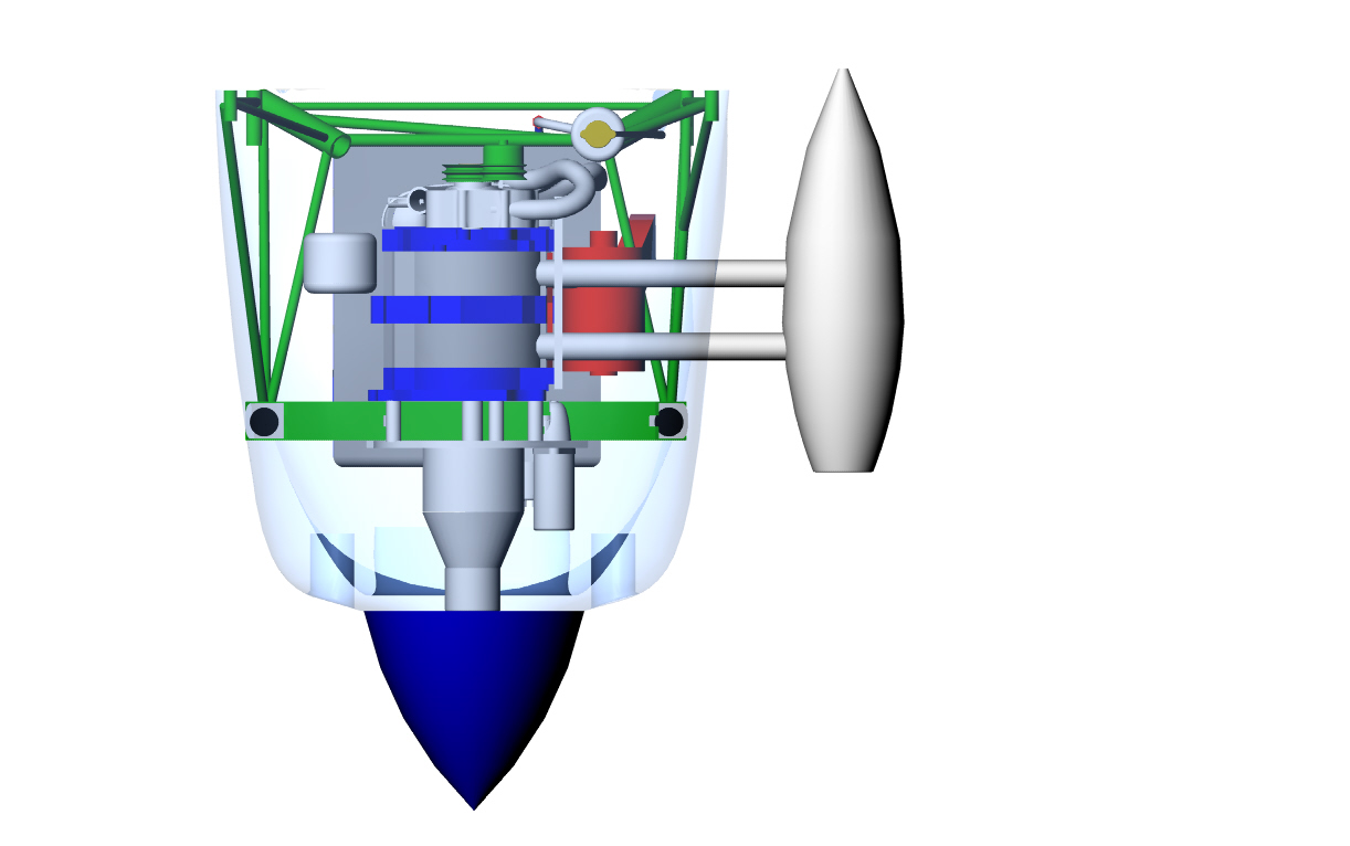
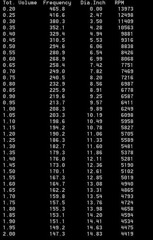
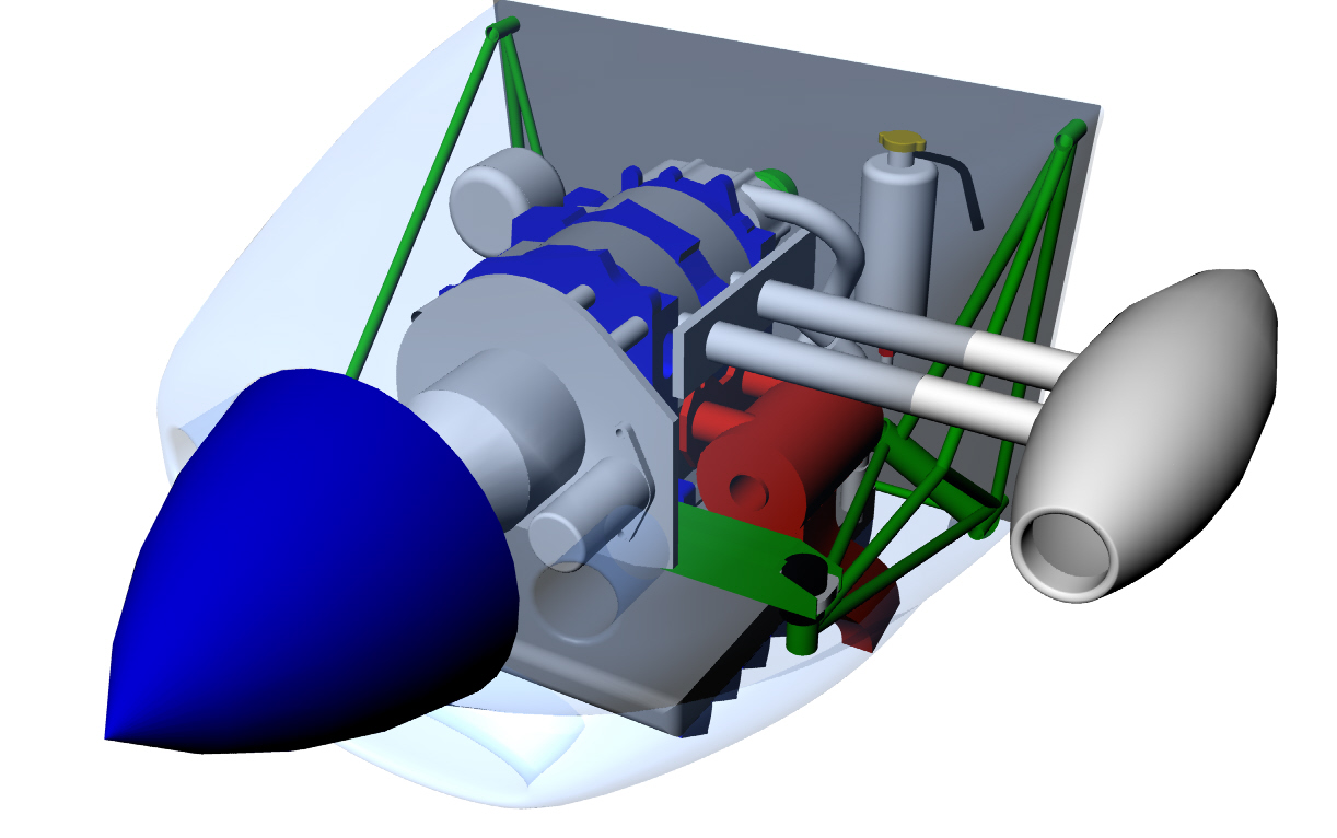
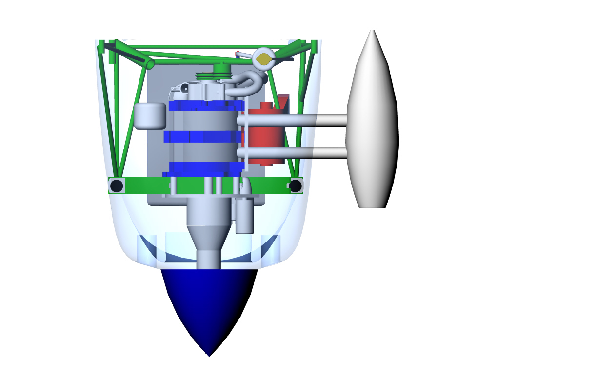
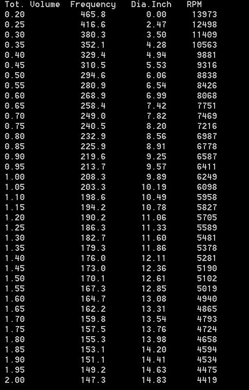
I did some adjusting of the basic condition's on the Helmholtz
resonator intake manifold to reduced the required diameter of the
plenum and lengthen the runners to 18 inches from 12 inches.
This would put the plenum outside the cowl which is not
bad for a ram air scoop. Something like all of this.
If my math is right I think we can conclude the Helmholtz
resonator intake manifold is a lost cause.
If somebody else wants to take a stab at this
please do.
Paul Lamar ...No rotor no motor.
The Rotary Engine NewsLetter. Powered by Linux.
ACRE NL web site.
http://www.rotaryeng.net
Copyright 1998-2006 All world wide rights reserved.