Rolf,
Unlike the discussion above I will fix the ring gear and take power
out of
the planetary cluster. The cluster would be attached on the prop shaft
and
be supported front and back on bearings. How would I calculate the
load the
planetary gears will be seeing? Total torque divided by the total
tooth
contact area? My engine will be putting out over 200 ft/lbs of
torque at
max rpm. With a supported prop shaft I believe the loads on the
bearings
will be from torque transmission and the centrifugal force of the
planets
themselves, right?
Also if I understand it correctly the gear line velocity is
circumference
times rpm. Calculating it from the Bell sun gear in feet that is
377mm /
304.8mm = 1.24 ft. 1.24' X 8200 rpm = 10,168 ft per min?
Mistral's unit at a 8000 designed redline with a slightly larger sun
gear
would not be far off this figure. You mentioned maximum line speeds of
5,000 ft/ min. Is that figure for light duty gearboxes?
Thanks
Doug,
You have a fixed ring gear and rotating planets. Give me the dimensions
of all the gears, DP and pitch diameter and we can calculate it
together. As already mentioned, it is pitch diameter times pi times rpm
/12. Pitch diameter in inches, pitch line velocity in fpm.
Since the pitch line velocity of all gears is the same, one need to
calculate just one. Best is the ring gear and the output speed or
propeller speed. The gear ratio is thereby irrelevant. The torque load
is also the same on all gears. The load per tooth is divided by the
number of planets.
The bearing loads are essentially torque divided by radius. The
centrifugal force of the planets only need be considered on the planet
bearings, for the output shaft they cancel each other out through equal
spacing around the circumference.
Rolf
The centrifugal load of the rotating planet assemble is
contained by the ring gear and the separating tooth forces.
Paul Lamar ...No rotor no motor.
Hi Rolf,
Here is the info again on the Bell 47 gear sets.
*Diameter is measured at gear tooth contact point. All measurements in
mm.
Name teeth number diameter gear width
Sun 46 120 27
Planet 23 57 22
Ring mm 92 234 25.4
Proposed input max rpm = 8200
Proposed max hp 343Hp
Proposed max input torque 220 ft/lbs
The planet gears tooth dimensions from the valley to the top of the 2mm
wide flat top is 5.9mm. The teeth are 4.6mm at their widest root.
In application Bell used the inner part of the hardened gears as the
bearing
race. A hardened collar (sleeve?) was placed over the gear shaft to
become
the inner race. This was 1950's technology and designed for low rolling
speeds but great torque. Keeping them center in the race where thick
washers on the outside and a fiber cage on the inside. TBO on the whole
craft was 1200hrs. The fiber cages lasted about 300 hours. Perhaps on
later
models Bell improved the bearings cages.
The inner hardened roller race that fits on the gear shaft is 23 mm in
diameter. The outer part of the bearings (actually the inner part of the
gear itself) is 39mm. The recess axially dimension to the central
inner rib
is 9 mm. Therefore the central rib must be 4mm wide. 22 - (2X9).
Calculations of bearing loadings:
Please check I am on the right track here.
The sun gear has to transfer a maximum of 220 ft/lbs torque at full
chat.
Most likely less. The torque output to the prop shaft with the 3:1 ratio
would increase to about 660 ft/lbs. Each of the six planetary gears
would
see 110 ft lbs. on what is basically a 2.5mm x 22mm (or 55 square mm) one
tooth contact area. The bearing is seeing 110 ft/lbs divided by the gear
28.5mm radius which works out to 3.85 lbs distributed over a line 18mm
long
contact line.
In conclusion. I believe I will have to have new planetary gears made and
ground with different internal bore specs to accept a standard high speed
sleeved roller bearing. Perhaps to increase bearing contact surface
area 22%
the internal gear rib will have to be eliminated. If gear deflection
strength becomes an issue the bore can be reduced in diameter slightly.
Depending on the design of the gear case the gear also can be widened
a bit
more thus giving even more bearing surface area. Presently the hand
inserted
roller bearings are held in place by two 3.2mm (one on each side) thick
spacer washers.
The housing has several ports to direct a stream of oil at the
planetary set
and at the front bearing. Since this design unit was meant to fly on a
helicopter I would like to find a way to introduce pressurized oil
through
the sun gear.
For pressurized oil into the prop shaft the Bell unit offers several
possible locations. The easiest manner would be to feed it into a
slightly
thicker outer collar that contained the proper shaft seals. This would
be a
'two birds killed with one stone' possibility. The present collar is
about
25mm thick.
All in the all the unit is rugged, compact and the case designed to
take the
large lateral transient loads placed on it which I believe my plane will
require.
Doug Fir
And too big to run at 8200 RPM.
Paul Lamar ...No rotor no motor.
Doug,
Here is the way I would look at it: the 46 tooth sun gear rotating at
6000 RPM drives the 23 tooth planet gear at 12000 RPM. It does not
matter that the planet is rolling inside the ring gear. For the planet
bearing load estimate, I would say the 660 ft-lb prop torque is
transmitted to the planet carrier at the radius of the planet axles,
which appears to be about 4" or .25 ft in your photos. The torque
divided by this radius and by the six axles gives a radial bearing load
of about 440 lb per axle. The compound motion of the rotating planet
gears revolving in the carrier tends to make the bearing needles bunch
toward one side (Think of a carnival ride like the "Round-Up" or
"Twister" where you sit in something that rotates about its axis while
the whole ride is revolving.). So, you need a caged needle bearing.
Preferably one that has a large contact surface between the cage and the
needles. The easiest approach would be to find a drawn case, caged
needle bearing that would work with your existing planet axles and meet
the speed-load requirements. Then, grind that partition out of the
planet gear and bush the gear to fit the needle bearing. It looks like
your axles are around 5/8" diameter. A quick look at an SKF catalog
indicates it is probably feasible to get 1200 to 1500 hours life on a
caged needle bearing of this size with this speed/load.
The pitch diameter of the planet gears looks to be about 2.3". That
would give a pitch line speed of 7417 ft/min. With continuous oil
spray, that speed is probably OK. Here is a photo of how the Solar T-62
turbine planetary is oiled. The ratio is 10:1 and it runs with a pitch
line velocity around 12000 ft/min. The sun gear is not present, but
you can see the three brass tubes that squirt oil on the gears just
before they mesh.
Aubrey
Great picture Aubrey. Did you take it?
Good analysis. I am surprised T62 APU operates at that pitch
line velocity. I guess that is about right since it is rated at
60,000 RPM and the pinion gear is tiny. Around 3/4 inch
in diameter. Glorified turbo charger :)
I think it does matter if the planet is rolling inside
the ring gear and power is taken from the
rotating planet carrier.
I think that reduces the pitch line velocity.
In the case of the T62 the dwg of which I attached the
shafts of the planet gears are fixed to the case so the
pitch line velocity is indeed 12,000 FPM.
The output shaft of the T62 rotates in the opposite
direction to that of the turbine/compressor shaft.
A agree with you on the torque analysis but Doug is
shooting for 3,000 hours TBO. In a rotating planet
carrier the loads on the needles are more complicated
so that case is not covered in the bearing manuals.
I agree a cage will help. The fact of the matter
is the Bell box is not designed for 8200 RPM input.
My guess is something like 300 to 600 RPM in and
100 to to 200 RPM out.
Paul Lamar
Aubrey,
Thanks for putting a positive spin on my attempt to use the Bell 47.
Your estimates of the components dimensions were pretty close.
The planet gear size you quoted is about right but the radius to the planet
gear axle is 3.5" and the planet gear shaft about 15mm in diameter meaning I
would have to find a metric needle bearing. Great idea on putting the
bushing outside the bearing. I will eventually get a new set of gears ground
once I know what the material specs. are. Question: Have needle bearings
every been used in a piggy back manner? Meaning one placed within the other
to spread out the loads?
This unit is going on the test engine while the 3000 hour life Mistral is
claiming with similar planet rpm speeds is immaterial. For a commercial
product that is an admirable goal and would be a great. Frankly if the
needle bearings had to be changed at 1000hr intervals that would be
acceptable to me because it is such a simple quick operation. I fully expect
the test engine and PSRU unit will be broken down and reassembled many many
times during the 200 hour test program.
If this gear box gets me through the on the ground engine test program that
would be good. If in the process I need to improve and recast the case then
I'll do it and I'll have a unit I can fly with. I will have a dedicated
pressurized oil system and cooler as I know that is critical for high line
speeds.
............
I just got off the phone with Dave Garber and he told me Bell engineers
thought the case would handle the high power/rpm loadings. They understood
Dave's aircraft application. Dave has about 50 hours of running the engine
on the ground and about 2 hours in the air, with a maximum flight level of
4500 MSL. All 20 flights were short because of engine cooling challenges
which he finally worked out. He did say that the engine was never was
pushed over 4500 - 5000 rpms.
He held down rpms to limit performance and because of cooling issues. He
took the plane off at these rpms but with about 50" of boost and he still
had the plane going 180mph with the landing gear down. Dave wants to push
the engine speed up to 8400 for the Reno race but I informed him that the
oiling, and bearing issues would need some 'work' to do that.
I'm not given up on this unit yet. Surely this unit has a future, after all
here is a website and a guy name Paul Lamar that introduced it to me:)
http://www.rotaryeng.net/Bell-47-GB-on-rotary.jpg
Doug Fir
Yea 15 minutes around the pylons at Reno :)
It is not so much the design is that far wrong. It is a question
of cost benefit. When you start talking high speed
high precision planetary gear sets in small quantities you
are talking big bucks.
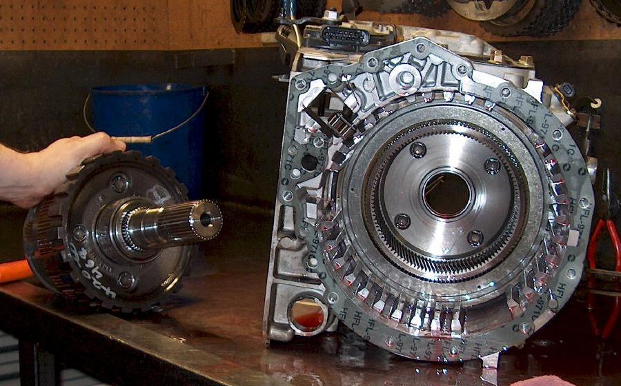
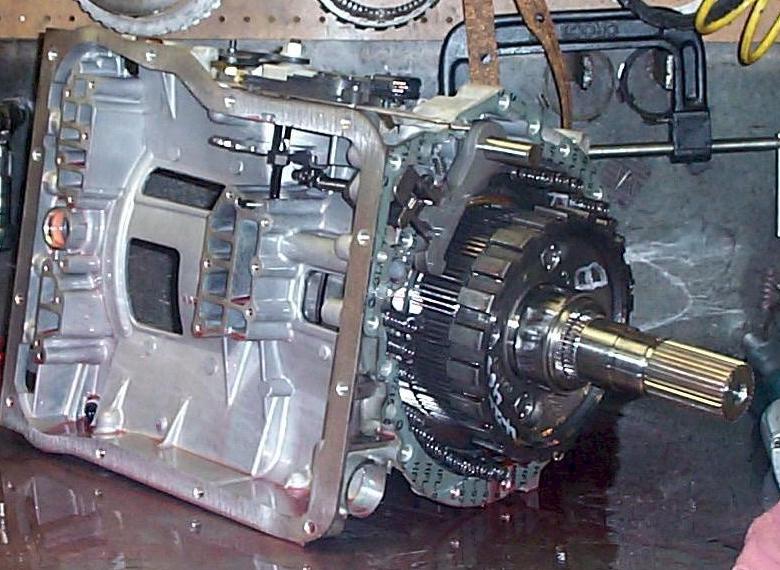
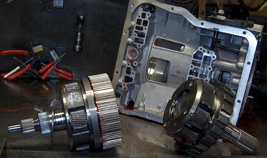
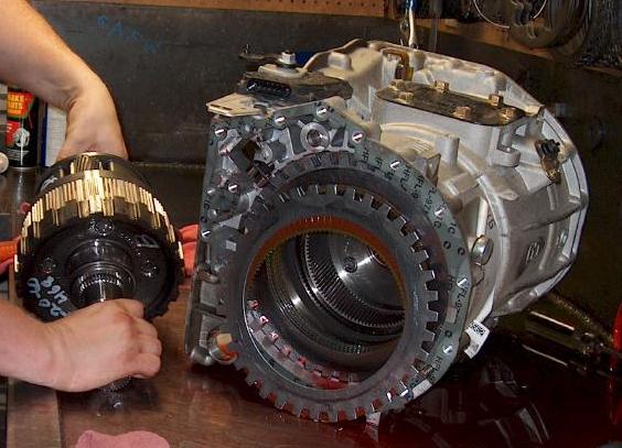
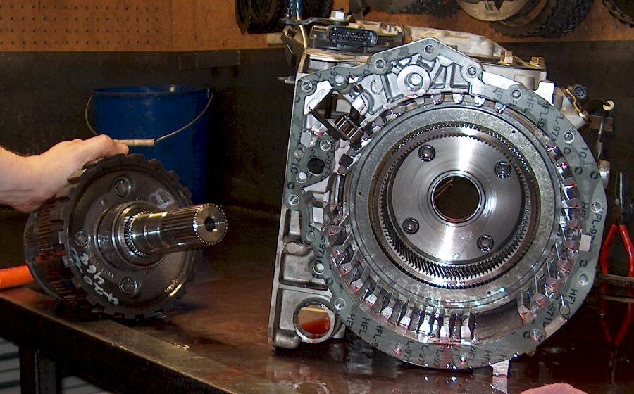
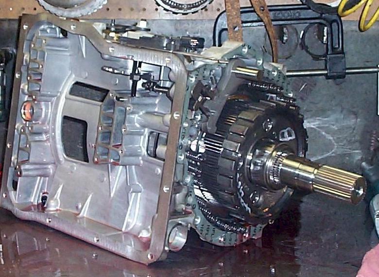
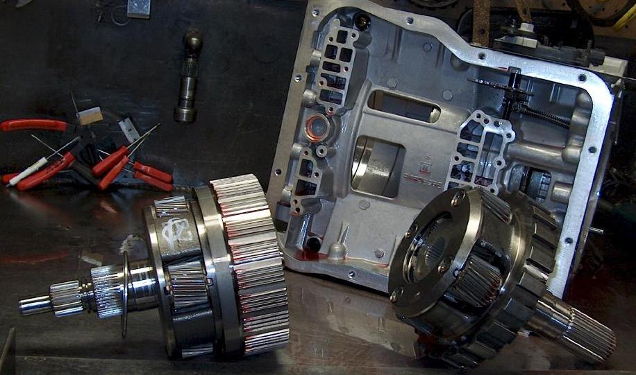
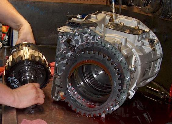
The Ford planetary on the other hand has untold zillions of them
running around the roads of the world for the last 40 or
so years. Many in trucks. Not only that there is another zillion
scaled down and made by Jatco in Japan. If you have driven a
Japanese car with an automatic transmission it was probably a Jatco.
There there are hundreds that have been sold by Ross,
Tracy and others for aircraft use. I have never received
info from somebody that has worn one out (if it was properly
installed) in the last seven years.
If you are a Chevy man and not a Ford man you could use
a planet set out of an Allison auto TX for trucks.
http://tktsales.com/
http://transmissiontech.net/
http://www.westernbranchdiesel.com/transmissions.htm
Automotive auto transmission parts are a better fit
for our use than a low RPM helicopter gear box.
Paul Lamar
The Rotary Engine NewsLetter. Powered by Linux.
ACRE NL web site.
http://www.rotaryeng.net
Copyright 1998-2006 All world wide rights reserved.