Paul,
I've been looking through the Kinsler catalog and they have
everything
you need to put together a dead simple, reliable mechanical fuel
injection system for not much money -- maybe less than an Ellison
carb.
Constant flow fuel injection is used on aircraft piston engines and
works just like it sounds -- there is a constant spray of fuel coming
out of the injector nozzles, unlike the timed EFI and some mechanical
systems for cars.
Constant flow is not great for cars, but perfect for airplanes,
because
you are running at steady-state rpm and power most of the time.
Have a look at the attached Kinsler Fuel Flow Diagram. The system
works
like this: a mechanical fuel pump driven off the engine supplies more
fuel as rpm increases. It sends the fuel to a barrel valve that
distributes the fuel to the individual nozzles at the intake ports.
The barrel valve is kind of like a spider in aircraft FI systems,
but it
is directly linked to the throttle, so as the throttle is opened, the
barrel valve is opened as well, allowing more fuel to flow to the
ports.
Fuel metering is accomplished upstream of the barrel valve by
putting a
restrictor jet in a return line that goes back to the tank. So
the fuel
coming from the pump has two places to go, the barrel valve that
leads
to the engine nozzles -- and the restrictor jet. The more fuel that
flows through the restrictor jet, the less fuel goes to the engine.
Leaning is accomplished by varying the size of the restrictor jet. A
bigger jet means a leaner mixture because it allows more fuel to
circle
back to the fuel tank and less to the nozzles.
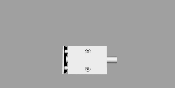
Kinsler has a cockpit adjustable mixture control that lets you dial
different jet sizes, as shown in the attached pictures. However, the
same thing could be accomplished with a simple ball valve, like
the Home
Depot valve that Paul is implementing. It would be controlled by a
Vernier control cable. This way no fuel has to go through the
cockpit.
The barrel valve is available with a minimum of four ports, so
you can
either put two nozzles on each P-port runner, one on each four-runner
manifold, or block off two of the ports and use one nozzle on each
P-port runner. I would use two nozzles per runner to get better
atomization. Also the fuel flow from two nozzles should be about
right
for a single rotor. Same thing with the fuel flow of the 4-port
barrel
valve.
You could use Paul's slide throttle with this system or you could use
Kinsler throttle bodies which already have the bosses for
attaching the
nozzles. If you roll your own you have to weld up some nozzle bosses
onto the runners. Btw, the Kinsler bosses can accept both the
constant-flow and EFI injectors.
This system can be used with a turbocharger or supercharger
because you
can run it with high pressure. You could get significant evaporative
cooling effect by placing the nozzles close to the engine and
spraying
the fuel right at the rotor. I would guess that you could
probably run
10 psi of boost without having to go to an intercooler.
In a normally aspirated engine you can run it at lower pressure.
It also
doesn't need heat, since icing is not possible. It provides all the
advantages of fuel injection in terms of precise metering and mixture
distribution.
This should make for a very dependable, completely mechanical system
that is not dependent on electrical, control boxes or computers.
If you
implement the flywheel magneto as well, you will have a real aircraft
engine.
You can download the Kinsler tech catalog here:
http://www.kinsler.com/catalog.htm
Regards,
Gordon.
Gordon
Very interesting. Good going.
One minor point though.
Please be advised that a ball valve is good as a shut off valve but
makes a
terrible leaning valve. For example the flow curve is like a J
curve. It's
design merit is in the low flow resistance when all the way open and the
ability to shut the flow off quickly. A good use would be the
emergency shut
off valve. For metering you need a metering valve or commonly called a
needle valve. The needle come down perpendicular to the flow and into a
tapered valve seat. Excellent fine adjustment for gas or liquid flows.
I have lots of experience using both of these valves with corrosive
gas and
liquid flows.
Doug Fir
Have you used them with a vernier leaning cable?
No problem. Just get a control cable you can twist
to adjust the needle valve. Do you have any
brands you can recommend or do we have to make one?
Paul Lamar ...No rotor no motor.
Doug,
Thanks for the scoop on the ball valve. Right after I posted this I
started thinking about the ball valve and began to suspect that it
might not be very good for leaning. A great shut off valve though.
A needle valve sounds like just the ticket -- hopefully there are
off-the-shelf items that will fit the bill. If not, you can always
use the Kinsler jet selector. Not as precise because it is stepped
rather than infitely variable, but still will work.
Regards,
Gordon.
I think the ball valve is not any more nonlinear than the round hole
in the slide throttle. One may get the impression it is hard
to adjust because the lever only moves 90 degree from full
on to full off while a threaded needle valve takes many turns
from full on to full off. The vernier push pull leaning cable to the
rescue. What the vernier does is allow super fine adjustments
by turning the knob. Much like a needle valve. I know some
of you have flown airplanes without vernier mixture knobs. Once
you have used one you will understand how well they work to
adjust the mixture to a fair the well.
IMHO the answer is lengthen the lever arm on the ball valve
until it travels 3 inch's on the end for a 90 degree
angular change. A lever about 2 inches long should do the
job.
However I am still open to using a needle valve if
somebody can come up with a practical design supplying a
3D drawing of same. A 2D sketch will suffice. If it looks
good and looks like it will work I will do a 3D.
------------------------------------------
OK I had an idea. We can make this out of aluminum tubing.
Three inch long needle. The valve seat is pressed in from
one end and the intake and outlet fittings are welded
or bonded on with JB Weld. Make two. One for each rotor.
The only draw back is the leaning knob works backwards.
push for shut off. Pull to richen and push to lean.
Paul Lamar ...No rotor no motor.
Paul,
Sorry to be late in replying. The boss had me raking leaves all day. Trust
me on the ball valve. You will be surprised on how unstable it is as a
metering valve. The reason is the opening cross sectional area is very non
linear. In use it seems like the flow goes from 10% to 80% in a few degrees
of rotation. Needle valves should be available in any valve catalog.
Yes vernier cable has the fine thread adjustment on the instrument panel
mount end I believe. C-152 had them but my C-150 has a Micky Mouse spring
clip. You pull and pull to overcome the resistance and suddenly you have
pulled too far. Makes for real attention getting when the engine starts
sputtering high over rugged northern Arizona terrain:)
OK of course pull to lean. I have an idea on how to make it. Give me about
6 hours and then I'll work on it tonight on Rhino. Lets see two needles one
inlet two outlets. The same principle will probably work for a bypass
mechanism for the constant spray injector. Now its 15:30 and still daylight
so the boss has my next assignment waiting for me. Probably splitting wood
for the ofuro, deep bath.
Doug
Paul,
Ok here is the rough idea. A stainless plate has two needles 4mm dia needle
and one 8mm stainless drive shaft TIG welded together. The U-shape (piston
tupe) double seal (green) and the red Teflon sleeve is held in by a
retaining plate with four M3 machine screws.
The side view show a cut- away of the needles going into the seat. Actually
the drawing is a little off. The needle point and seat part should be
deeper than the port hole. When closed the port should only 'see' the
cylindrical part of the needle. Port holes can be sized according to your
maximum flow desired. The port has to be smaller than the diameter of the
needle of course. As the needle valve opens fuel to angles downwards
towards the tip of the needle and up the other side of the cone. As it
opens progressively more the cone shape cross sectional becomes progressively
bigger and hence less restrictive.
The inlet port would most likely be singular. This is done by drilling a
larger than port size hole down from the top intercepting both port holes.
This hole does not go all the way through. This creates a fuel chamber.
One larger inlet hole is drilled in the center equi-distant between the
valve ports and tapped for a pressure fitting. Then the top hole is plugged.
In application your cable end would screw into the female thread in the
drive shaft. Stainless moving on Teflon with a little grease is smooth.
Just like your printer. A spring could be include on either end
I didn't draw the steel mounting plate. It could be a double L and attached
to the body of the valve on almost any of the four long sides.
If the cable needs a support the one piece bracket could have another L
shape flange bent over to interface with the vernier cable. A compression
spring could be added on the needle support plate side do add some
resistance to leaning.
Doug.
Why two needle valves working in unison?
I suspect your missing the function of the needle valve.
It is only a fine adjustment on the mixture. One will do.
You can use two (one per rotor) but they must be individually
adjustable.
The slide in the slide throttle does the gross adjustment
to the amount of fuel as a function of the area of the
slide opening.
--
Paul Lamar ...No rotor no motor.
The Rotary Engine NewsLetter. Powered by Linux.
ACRE NL web site.
http://www.rotaryeng.net
Copyright 1998-2006 All world wide rights reserved.