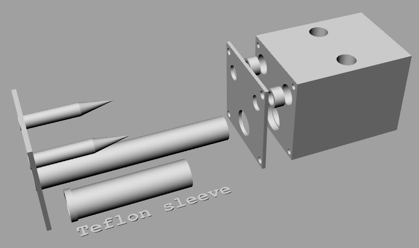
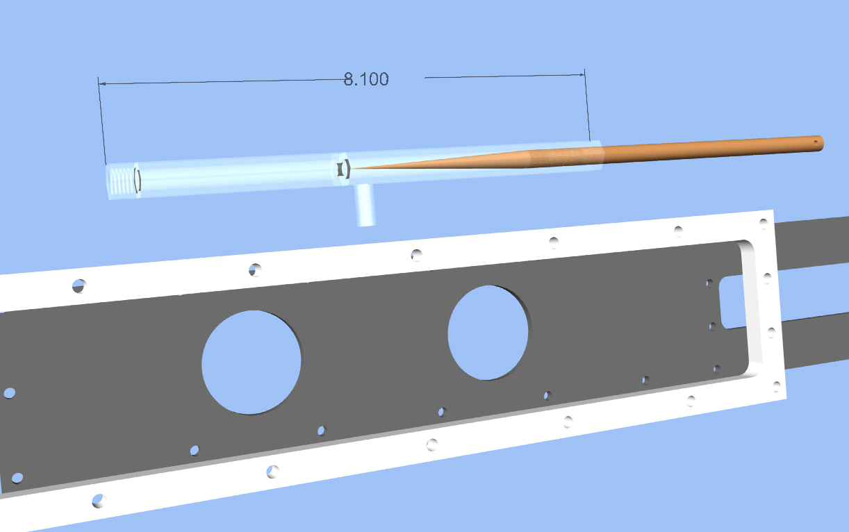
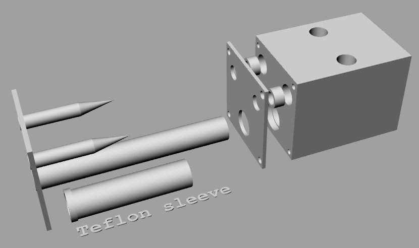
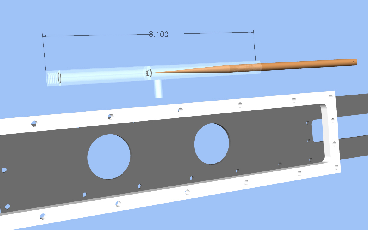
I suspect your missing the function of the needle valve.
It is only a fine adjustment on the mixture. One will do.
--
Paul Lamar ...No rotor no motor.
Paul
This valve idea I sent was more in responding to Gordon's post on the
Constant Flow Fuel Injection post thread about a separate injection system
but could also be be incorporated into your slide throttle.
As you have modeled the slide throttle, getting fuel to flow evenly to the
separate ports will be challenging to say the least. To assure this, both
passages from the point the fuel leaves the singular valve port must have
the same dimensions, lengths, bends etc. Hence two needle valves, each one
dedicated to a port on your slide throttle. IMHO the brilliant part of
slide throttle fuel delivery system is that fact that you have in essence a
variable size orifice system. I believe this was your original design. Say
at any time at least one jet and sometimes two opened. This allows you to
drill progressively bigger holes. I am not sure how this will be
accomplished yet but the idea has lots of promise.
Perhaps the double needle valve has a use in Gordons' way as well. Bear with
me a moment and lets examine this half baked midnight madness idea.
Gordon introduced a system that seems interesting and had many variables
introduced into managing fuel flow. The device he showed had a mechanism
that bypassed unneeded fuel through one of eight selected orifices thus
controlling the pressure and flow on the system. It seemed complicated in
the plumbing and because engine rpm and pump flow curves are never very
linear. In essence the multi-orifice valve becomes a little pressure
accumulator and the outlet orifices are part of by pass system.
One needle valve could do the same thing as well.
Background thinking:
As you might know, with the SeaWind, the standard LycCon engine mounted fuel
pump can not pull the fuel ten feet in length and six feet in elevation when
the airplane climbs to over 8,000' The system therefore needs a altitude
electric boost pump. Correct me if I am wrong but any mechanical based fuel
delivery system is going to have to be a back-up low altitude unit to keep
my feet dry :)
Hence high altitude flight depends on having electricity for me. If the
mechanical pump was served by an electrical booster pump then electrical
failure mode would mean a decent to under 8,000'. The mechanical pump
feeding constant flow, high pressure mechanical injectors could possible
operate with some sort of mechanical by pass valve. If you mechanically
adjust the setting of this valve (actually a screw adjusting spring
pressure) in essence vary the outlet line pressure and hence the flow
quantity. It becomes a fuel throttle.
Said another way the mechanical pump is over sized but reacts to pressure
head and by passes fuel from the outlet side back to the inlet side
essentially unloading the pump a bit and eliminating the need of a return
line. Nothing new here folks. Similar systems are usually built into the
carb. as a float (flow) or as a pressure regulator in Ellison I suppose. It
doesn't have to be though.
I think the ultimate efficient setup would be to have the electrical fuel
pump, small pressure tank and the pressure regulator installed in or around
the vicinity of the header tank. A analogous system would be how portable
air compressors or home water well pressurized systems work.
The pressure tank needs a sensor which tells the electric pump to turn on
and run until the fuel volume and pressure in the pressure tank reaches a
preset value. The pump doesn't run when there is no demand for fuel hence
the line pressure after the regulator remains low. In this case the fuel
pressure regulator is separate from the air throttle and can be linked
electronically or mechanically.
Perhaps for me a combination would work the best. That is a electrically
driven pump/pressure tank, with cut off sensor supplying the mechanical
engine driven pump. This way the engine mechanical pump could be biased
towards output pressure.
Darn now where did I file the picture of the 300hp P port racing engine with
the mechanical fuel pump and injectors spraying into the bell mouths?
Doug Fir
---------------------------------------------------------
"As you have modeled the slide throttle, getting fuel to flow
evenly to the separate ports will be challenging to say the least."
Not true if you use two separate leaning valves as I have already
suggested several times.
In fact you may not want to have fuel to flow evenly to the
separate ports. What you want is the RIGHT amount of fuel
to flow to each rotor depending on the individual characteristics
of each rotor. Typically the EGT's are not the same due to
many factors in most A/C installations. This is also true
for most EFI systems.
Yes the holes can be tailored but probably unnecessary as
the latest design uses many holes of the same size. More and more
are connected as the slide is opened. I have updated the
web site with the new design.
http://www.rotaryeng.net/bunch-of-holes-SLT.jpg
http://www.rotaryeng.net/bunch-of-holes-SLT2.jpg
http://www.rotaryeng.net/spacer-slot-detail.jpg
Your needles are too short for a typical 3 inch travel leaning
cable and rapid control. The advantage to the vernier AND three inch
travel needles is you can make rapid gross changes or cut off the
fuel completely by pushing or pulling the knob.
Twisting the knob gives a fine mixture adjustment. You set the
mixture full rich for starting and you shut off the fuel supply
for stopping the engine. Just like any Cessna.
Your approach is way more costly. By using SS tubing and SS jic
1/8th plumbing fittings the cost of my needle valves can be just
a few dollars using only a lathe to cut the needles.
Mechanical rotary fuel pumps are expensive and they must be driven
somehow from the engine with the proper gearing.
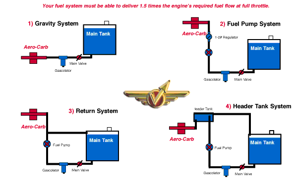
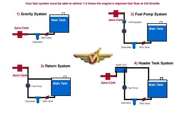
To implement a simple, low cost, low pressure system you have a
high tail that you could put a sump tank in with a stand pipe in
it that would return excess fuel to the main tank as in this
Aerocarb diagram. Use one or more cheap Facit electric boost pumps to keep
the sump tank full. A hand wobble pump would work in an emergency.
If the vents in your main tanks point forward they too could
provide dynamic pressure to help transfer fuel up to the sump tank.
The old air cooled VW bug used a similar stand pipe in the main
fuel tank. When the fuel level got below the top of the stand
pipe you switched over to another reserve line plumbed to the
bottom of the main tank.
I can sympathize with you on why you want a fly by wire system on
the remotely mounted engine on a SeaWind but even a
B747 uses steel throttle cables. BTW UAL had a cowl come off
an Airbus at LAX on take off. When the cowl departed it
took the fly by wire throttle control with it. The pilot
had to cut the fuel supply to the engine to shut it down
so he could land.
The picture you speak of is on the web site.
http://www.rotaryeng.net/mech-fuel.html
--
Paul Lamar ...No rotor no motor.
The Rotary Engine NewsLetter. Powered by Linux.
ACRE NL web site.
http://www.rotaryeng.net
Copyright 1998-2006 All world wide rights reserved.