I guess I'll have to jump in on this one. I did quite a bit of research
and experimentation on turbos. I have real experience with running them
up to 18000 ft. My plane has a total of 150 hrs of turbo time and 50
hrs N/A time. I really should update my website with a discussion of
turbo selection so I don't have to keep re-typing this...
I agree that the TO4B series is probably the best choice for size, cost,
and availability. Paul is right that the stock turbo will produce
sufficient power, but at that power level it is over speeding and will
not last long. That cannot be fixed by putting on a larger waste gate
alone. Turbo speed(in a given turbo) is simply a function of mass flow
( i.e. desired horse power) and pressure ratio. That is regulated by
the throttle (i.e. how much h.p. you use), not the waste gate. A bigger
waste gate will only reduce the back pressure created for a given
position on the compressor map. But given an altitude and power
output, changing the waste gate will not affect turbo speed, surge,
stall, over speed, or thermal efficiency.
The waste gate only determines what portion of the exhaust energy is
flowed through the turbine. So the idea is to feed the turbine only the
energy that is needed to create the desired boost. Anything more just
increases the back pressure and reduces the efficiency of the system
(different than compressor thermal efficiency).
In my plane, only the stock turbine housing will fit. It is amazingly
compact. I originally ran the stock series 5 turbo. It was good for 70
flight hours, of which only about 15 were high altitude/ moderate boost
hours. It died. My replacement (current) turbo is the TO4B 60-1
compressor attached to the stock turbine housing that has been reamed to
accept a TO4 p-trim turbine. After 80 flight hours, including at least
40 hrs of high duty, it shows no sings of being abused. This turbo is
capable of making at least 40psi of boost (MAP well above 80in. at sea
level).
I need a turbo that size for proper efficiency and compressor speed at
altitude, not high boost. Since I will never use that much boost I
opened up the waste-gate. The waste gate has been ported and the flapper
removed. In this configuration, full throttle at S/L will give me a MAP
just under 50", which is perfect.... I am only using the exhaust needed
to obtain the desired boost.
This translated to just over 30" MAP at 16k feet altitude and WOT.
Again, perfect. Minimum loss of efficiency from back pressure, minimum
loss from throttle body pumping. Aircraft Speed approaching Vne.
Compressor speed well into the green according to the compressor map.
It sounds like the end of the story, but I still plan some changes to
the turbo when I get around to it. I plan to put the flapper back in,
and aggressively clip the turbine blades. The waste-gate has another
important function in my set up. Besides bypassing unneeded exhaust, it
helps to regulate and smooth out the natural variations in boost. These
variations only really become evident when running WOT, particularly
when running lean of peak. With the flapper removed (waste gate passage
fully open all the time) I have found that I can either aggressively
lean the mixture, or operate at WOT, but not both at the same time. If
I try to do so, the natural variations in engine RPM have an amplified
effect on boost and engine RPM. i.e. a slight decrease in RPM leads to
decreased exhaust energy which leads to decreased boost which further
decreased RPM. It all happens rapidly and seems like someone is playing
trombone with the throttle. At less than WOT, the throttle valve tends
to dampen out these variations. The flapper valve on the wast gate
(connected to the stock automatic actuator) did the same thing when it
was connected. I am not sure why running rich also fixes the problem,
but it does.
So here is the IMHO Dave Leonard simple guide to selecting a turbo for
the aircraft 13B: A compressor in the size neighborhood of the TO4B
60-1 (since it is oversized and underused the exact size does not really
matter as long as it is in the neighborhood - check the maps, many are
in this size range). Then, the turbine should be as BIG as you can
fit... (A/R in excess of 1.0). Have some sort of automatic regulation
on the waste gate, then make the wast gate big enough and/or the turbine
clipping aggressive enough so that full WOT will give you what you
decide is the maximum MAP you want to be able to achieve (for the time
being I recommend less than 50" MAP at sea level).
The amount you need to clip you turbine blades will depend on the
turbine and compressor that you finally choose. A larger turbine and
waste gate is probably preferable to a more aggressive clip.
Alternately, a huge aircraft style wast gate with a normalization is
probably appropriate if you prefer.
BTW, keep in mind that if you go to an automotive guy to get the turbo
built they will try to talk you out of it. Very few of them understand
what you need, they seem to be too in tune with what the car guys
want/need.
And finally, regarding mass vs. volume for turbine sizing... My first
issue with the above discussion it that you discounted mass flow as the
preferred way to size the turbo. I initially (years ago) agreed with you
that volume flow seemed more approiate, and it will work (and some turbo
maps are in volume). But the density of the air does matter. The
reason is that we need some sort of standard reference pressure to use
when deciding how much volume we need in order to achieve the desired
h.p. from the engine. Since h.p. is mass dependent, I have found that
is far easier to use mass flow on the turbine maps. This then will
correlate directly to the proper higher pressure ratio for use on the
compressor map.
Another way to look at it: since the pressures are different in
different parts of the intake system, then volume flow is going to be
different depending on whether you are looking at compressor inlet,
outlet, throttle body etc... but the mass flow is the same throughout
the system. If you play with it long enough, you will see that mass is
the better measure.
David Leonard
Turbo Rotary RV-6 N4VY
My websites at:
http://members.aol.com/_ht_a/rotaryroster/index.html
http://members.aol.com/_ht_a/vp4skydoc/index.html
http://leonardiniraq.blogspot.com
Thanks for your input on this Dave. So far you have got more
out of the largely stock 2nd gen turbo than anybody else.
I agree with you on mass flow. So many air molecules
combined with so many fuel molecules equal HP.
You state:
"A bigger waste gate will only reduce the back pressure created
for a given position on the compressor map."
This is not clear. I am not sure I agree. If no other changes
are made a larger opening in the waste gate WILL change the position
on the compressor map because less turbo HP is going into the
compressor. The limit case is no exhaust gas going to the
turbine at all. The position on the compressor map will be at the
very bottom in that case.
I think not everybody wants 50 inches of Hg boost at sea
level or flat rating to 16,000 feet.
Suppose a larger (or different type) waste gate alone gave 29
inches of HG at sea level (no boost) and the waste gate was
gradually closed to get more inches of Hg boost at altitude.
In other words flat rating but maybe not to 16,000 feet as you have
done. Better yet a red line RPM was established for the turbine
and the waste gate controlled to keep the turbine within
the red line RPM. Would that not be cheaper than increasing
the size of the compressor to slow the turbine?
I think that would be a good starting point for most people.
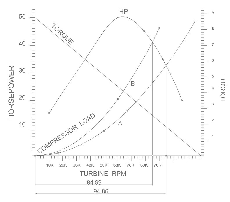
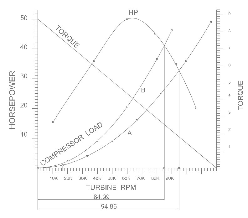
The HP of a given turbine is a function of the blade speed to
exhaust gas velocity ratio. Dynamic pressure if you will.
Dynamic pressure is both a function of velocity and air
density. As the blade goes faster than about 50% of gas speed
HP starts to drop as turbine torque is a linear inverse function
of turbine RPM. Chart 2. Therefore I agree that using a larger
compressor (A to B) reduces turbine RPM and increases the HP put
into the compressor IF the RPM is beyond the 50% gas velocity point.
Chart 4. Note the similarities with a combustion engine
and a propeller. The HP curve can be thought of as
potential HP. Only when the HP curve intersects the load
curve have you extracted any appreciable HP from the turbine.
Another good analogy is dyno load verses prop load.
One might get the impression this is a very complex subject.
One would be right :)
Paul Lamar
Thanks for jumping in Dave.
I have nothing against the maps that use mass flow. If you want a
turbo because you want to increase your horsepower you have to think
in terms of mass. The Garrett website gives good info on this. It's
a simple matter to figure out how much mass flow you need based on
your air-fuel ratio and BSFC. You can then look at the compressor
maps and choose a compressor that will give you the mass flow you need.
But what do you do if you don't want to increase your horsepower,
but want to carry your existing horsepower to a higher altitude?
Then you have to think in terms of volume, because you're going to
need more volume in the thinner air -- not more mass because you're
not after more power. (Same mass, more volume) And those compressor
maps are no help at all for us.
Still, it's no problem if you do the arithmetic. Then you can use
the mass flow maps just fine. The mass and volume relation is fixed
in the ideal gas law. That's why I posted the formulas. I have
reposted them here in a simple 4-step form. I will also put them
into a spreadsheet and that will make the calculations easier.
Thanks for describing your setup. With 50 inches of manifold
pressure it makes considerably more power than a normally aspirated
engine at sea level -- a ground-boosted aircraft engine, in other
words. Nothing wrong with that -- it's always nice to have extra power.
What I'm interested in though is a turbo normalized setup that
is dead simple from a flying point of view. A good example of this
is the Mooney 231 or Turbo Arrow, neither of which has any kind of
waste gate adjustment whatsoever -- either automatic or
pilot-controlled. Same thing on the Seneca turbocharged twin.
There is just a small pipe upstream of the turbo that bypasses some
of the flow. That's it. It's basically a fixed waste gate, but it can
be adjusted on the ground. (See attached picture). The turbine and
compressor are sized to achieve the desired boost and turbine speed
as you climb. This can be done just as easily on the rotary if we
choose the right size turbine and compressor.
Another simple setup is the turbo Skylane and Saratoga which do have
a waste gate that is linked to the throttle. You fly the plane just
like a normally aspirated bird. You push the throttle in for takeoff
and pull it out a bit for cruise.But you do have to monitor manifold
pressure more closely in climb and descent. A lot of STC'd
turbo normalizing systems use this setup too.
Notice that the waste gate is closed at takeoff. Why doesn't the
turbo over speed or the manifold pressure over boost? Because the
turbine is big enough that the sea level exhaust energy can't spin
it up. The exhaust energy is a function of exhaust speed across the
turbine, which is a function of pressure drop across the turbine,
which, in turn, is a function of the pressure delta between the
turbine outlet (which is ambient) and manifold pressure. This
pressure delta increases as you climb, provided you can maintain sea
level manifold pressure. So the exhaust speeds up, and the turbo
spools up the compressor, adding just the right amount of boost you
need to keep manifold pressure up -- provided you have sized the
compressor and turbine just right.
We can use this natural balance, if you will, to our advantage in
designing a turbo system that needs no pilot control whatsoever. I
like the simplicity of this approach because I find that simpler
systems make for more enjoyable flying. That's why you see the move
toward single-lever control -- something turbine pilots will tell
you is a very good thing.
Regards,
Gordon.
Here is a good site for the basics of turbo charging.
http://www.turbobygarrett.com/turbobygarrett/tech_center/turbo_tech101.html
http://www.turbobygarrett.com/turbobygarrett/tech_center/turbo_tech102.html#b
http://www.turbobygarrett.com/turbobygarrett/tech_center/turbo_tech103.html
The problem with all the sites I have been able to find
so far is they lack the real information how much power can
I get out of the turbine at different RPMs as a function of
mass flow?
The other bit of information I need is how much power or torque
does the compressor consume as a function of RPM?
Knowing that data it is a simple matter to determine
at what power level out of the turbine or turbine RPM
will intersect the HP required to drive the compressor
at the same RPM.
Paul Lamar ...No rotor no motor.
The Rotary Engine NewsLetter. Powered by Linux.
ACRE NL web site.
http://www.rotaryeng.net
Copyright 1998-2006 All world wide rights reserved.