Hey guys please look this over and tell me what you think.
Is there anything missing? Improvements? etc.?
Paul Lamar
----------------------------------------------
The Wankel rotary consists of a three sided rotor moving in a modified
oval
chamber or rotor housing. The shape of the chamber is a mathematical
construction called an epitrochoid. These curves were studied by Durer
(1525), Desargues (1640), Huygens (1679), Leibniz, Newton (1686),
L'Hospital
(1690), Jakob Bernoulli (1690), la Hire (1694), Johann Bernoulli (1695),
Daniel Bernoulli (1725), Euler (1745, 1781). An epitrochoid appears in
Durer's work Instruction in Measurement with Compasses and Straight Edge
(1525). Nothing new here.
The Wankel engine housing configuration was designed by Bernard Maillard in
1943 and it is not an epitrochoid. Admittedly the Wankel style rotary engine
designers today use the epitrochoid for a housing but it is not precision.
The apex seals must reciprocate within the groove to keep constant contact
with the housing surface. Study of the Jan Norbye Wankel engine book page
493 will show the precision design copied by Felix Wankel in his basic
patent drawing covering the Wankel rotary compressor shown on page 88.
Bernard Maillard drew the exact path that each apex of the rotor draws as it
is forced to swing over the stationary gear by the eccentric shaft. The
stationary gear in the Mazda has 34 teeth and the rotor has 51 teeth
therefore the rotor can only advance 17 teeth or one third per e-shaft
revolution.
The Bernard Maillard Fig. 4 shows the diameter of the eccentric at the
center with points at the 6, 9, 12 and 3 o'clock positions.(Note that he is
drawing two configurations at the same time in this instant please only
refer to the outside) The rotor is a 1.5" radius.
He drew a vertical 1.5" line from the 6 o'clock position
He then moved the starting center point 90 degrees to the nine o'clock
position and drew a 1.5 " line rotated 30 degrees.
He then moved the starting center point 90 degrees to the 12 o'clock
position and drew a 1.5 " line rotated 60 degrees.
He then moved the starting center point 90 degrees to the three o'clock
position and drew a 1.5 " line rotated 90 degrees.
What he did was show the correct system to draw one quarter of the housing
by moving points three quarters around the eccentric diameter. 3/4 times
four is three. The process for creating the precision housing takes place in
following the above directions for three complete revolutions.
Simply put for every three degrees of rotation clockwise from the six
o'clock position you rotate the line one degree clockwise the ends of the
line draw the housing.
The good news is that the Mazda housing has a steel liner under the
chromium that is sufficiently thick so that it can be ground to be precision
to re-chromium
The stationary gear has a huge function in the production of torque in the
Wankel engine Instead of a .591" torque wrench turning the e-shaft from
center we have a point of the rotor locked on a stationary gear .591 inches
opposite the e-shaft lobe and the combustion pressure is applied against a 3
to 4 inch radius rotor. The stationary gear provides a anchor for a 4.591"
pry bar to turn the e-shaft centered 1.182" from it.
Kenneth McKenzie
Very interesting Kenneth. Thanks for uploading that.
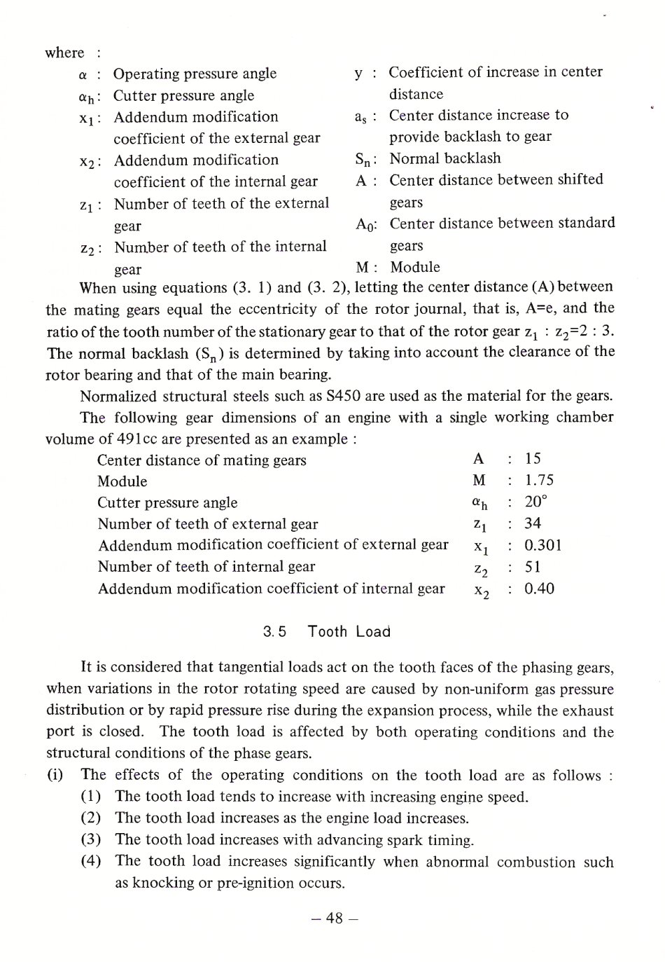
Here are the loads on the gears as claimed by Mazda in Kenichi
Yamamotos book Rotary Engine page 48. This I think trumps
the work that Maillard dis as far more structural factors were taken
into consideration. Mazda later experienced some gear failures and
the stiffness of the rotor gear mounting was changed to solve the
problem. As I recall they went from six small roll pins to nine
small roll pins.
Paul Lamar
The Rotary Engine NewsLetter. Powered by Linux.
ACRE NL web site.
http://www.rotaryeng.net
Copyright 1998-2006 All world wide rights reserved.