> Bill Eslick has run a bunch of interesting prop tests and
> published the data on his web site.
http://www.weslick.com/
> I reproduced some of it here and added some comments.
> The airplane is running into a brick wall at 165 MPH.
> Increasing the power does not help and just burns more
> fuel. It does not result in an increase of airspeed.
>
> My theory is the prop tips are stalling and running
> into the high drag transonic region at the same time.
>
> Quoting Bill:
> "I used a Props, Inc. 67 x 68 wood prop, a Felix Bi-Cambered
> 68 x 72 wood prop, and a Warp Drive three-blade ground adjustable
> carbon-fiber prop."
>
> Quoting Jordonoff:
> "If the propeller were turning in solid material, as is the case with
> a screw in wood, it could act without slipping, and so the distance
> traveled in one revolution would be equal to the theoretical travel
> of the propeller. Inasmuch as the propeller is turning in the air,
> however, there is a certain amount of slip; there fore its actual
> travel distance falls short of its theoretical travel distance."
>
> The ratio of how far it would screw into wood to how far it would
> screw into air is called the Advance Ratio. IMHO these props are
> at the limit of the advance ratio.
>
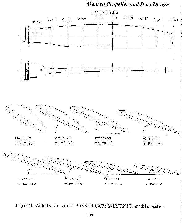
> The Warp Drive have no twist so the tip drag is higher.
>
> The tip thickness is as follows.
> Felix: 0.235" Props, Inc: 0.420" Warp: 0.272"
>
> I am guessing here. The solution might be more blade area with
> a shorter prop. The Warp drive blades can be modified by
> cutting off the aft part of the blade at an angle and sanding
> them in such a way as to reduce the tip angle of attack and hence
> the drag. However one would probably have to add another blade.
> I'll do a 3D shortly
>
> What is your theory on what is happening?
> Paul Lamar
The Warp Drive prop has very little twist - about 13 deg and was designed
and
optimized for ultralights and 100 mph operation. At higher speeds, the
inboard
sections of the prop are actually going into reverse thrust. Look at the
prop
and see if you have any bugs on the forward face of the prop. There should
be none, only on the back of the prop (this is near the hub).
I had the same problem with my 125 hp Soob EA81 powered Europa and
after doing the research went to a Catto custom fixed pitch. WOT speed
instantly jumped from 150 to 175 mph with no other changes. Climb stayed
the same.
The Catto has 40-45 deg twist at the root. This is so at higher speeds, the
hub area is still at a positive angle of attack to the relative wind.
I had no idea what was going on and I emailed Stuart Gort at Powerfin
Props and he was
very helpful with the following:
The Powerfin B-model has only about 2 more degrees of twist than the
Warp. The twist is important on your application because as you approach the
fast part of the flight envelope, the inboard sections of the prop begin to
go into beta mode. This means the air is being accelerated over the lower
camber faster than over the upper camber, essentially making reverse thrust
(or at least making enough drag to be the main factor in achieving
equilibrium - no more acceleration). Our prop, because of the 2 more degrees
might have some positive effect but I wouldn't bet the farm on it. Chances
are that any improvement would be negligible. For airplanes in the 135 mph
range, a proper design might have about 40 - 50 degrees of twist from the
tip to the most inboard definable sections. A Warp, at 64" has about 13
degrees. So, the lack of twist on the Warp and the resulting drag on the
inboard stations is certainly slowing you down but there is no off the shelf
design out there yet that can well accommodate your plane.
Stuart Gort
Powerfin Props
GLENN CROWDER
The point here is modifying the Warp drive prop
you might have instead of spending big bucks on
new props until you find one that works.
That is if you can even find a properly twisted all carbon
blade with sufficient blade area to absorb the rotary HP
that can be ground adjustable in pitch.
The Warp Drive blade can be set up in a mill at just the right
angles and the bottom milled off flat. If you keep
the set up support you could mill all four blades
which is what I think one is going to need for blade area
when you cut the prop down to about 64 inches dia. or so.
(To lower the tip Mach number.)
No doubt about it. It is a compromise and far from
perfect. Final shaping can be done with a block sander.
I am not sure this is going to work but it might be worth
a try. Cheaper than up grading one's PSRU to a 2.85:1.
BTW Perry Mick do you think you can duplicate Bill Eslicks
test with your current prop? As I recall you are also
running a 2.17:1 PSRU. That will give us some more data
to go on. These airplanes should be going
faster with all that HP.
-------------------------------------------------------
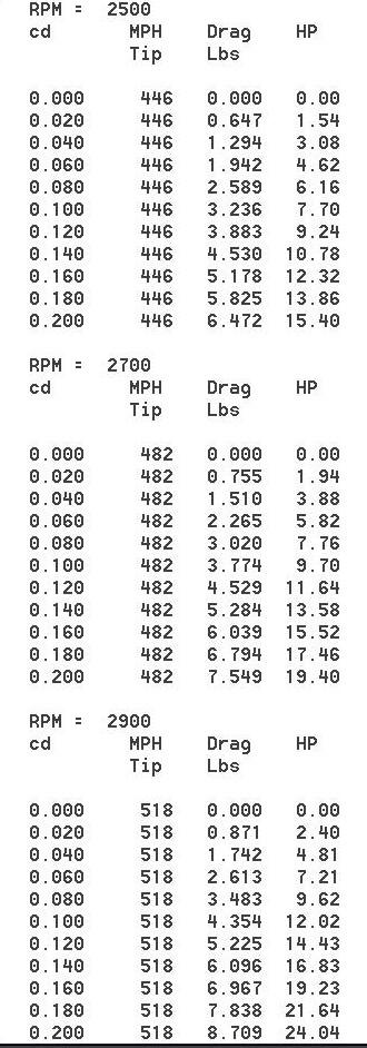
To illustrate the importance of the prop tip on the overall
efficiency of the prop I wrote a short Quick BASIC program
to calculate just the HP consumed by a very small 3 inch by
3 inch section of the blade tip. The last segment of the blade.
The diameter of this prop is only 61.5 inches. I can do a whole
series of diameters however. The larger the diameter the worse
the drag at a given RPM. Particularly at high speeds were the
forward velocity of the airplane adds to the vector sum of the
tip velocity. Not done yet in this program. If one does this
one winds with a lot of tables or curves.
The drag coef. (cd) used are from Von Doenhoff classic book "Theory
of Wing Sections". The total HP consumed by the prop is the
addition of the HP consumed from all the segments from the hub
to the tip. As you can see the HP consumed rapidly increases
as the RPM and the section drag coefficient goes up. This is
why efficient props are tapered and the tips are thin. The thinner
the better. This is where carbon fiber comes into the picture.
Carbon fiber has a higher strength to density ratio so it is ideal
for anything that rotates at high speed. The blade is also twisted
to near zero angle of attack and, in some cases, are swept back
to minimize tip transonic drag.
There are some spread sheets around that do this but I find Quick
BASIC to be quicker. If anybody wants to use QB or learn it
let me know. IMHO it is the easiest programming language to learn of
all the programming languages. If you wish to try doing a spread
sheet I can send you the source code for this calculation so you
can see and use the formulas I used.
Paul Lamar ...No rotor no motor.
The Rotary Engine NewsLetter. Powered by Linux.
ACRE NL web site.
http://www.rotaryeng.net
Copyright 1998-2006 All world wide rights reserved.