>
>> Kenneth
>> Did a little more study of splines and find
>> that 24
>> pitch is standard. That dictates a shaft
>> diameter of
>> 1.125 with 27 teeth or 1.25 with 30 teeth. Do
>> you
>> think it feasible to shape internal splines in
>> lobes
>> using EDM to minimize distortion and stress?
>> Also did
>> a quick calc of torsion and find a 1" shaft
>> with
>> active length of 8" will windup about 1 deg
>> under
>> 500#' torque. Don't know what's acceptable or
>> if I
>> analyzed correctly. What do you think.
>> regards, Robert
>>
>> Robert,
>> You are correct, I don't believe you would ever have
>> success broaching a
>> spline. I personally think persuing this method
>> would be folly. By the
>> time you have made the structure tight enough to be
>> workable it would be
>> cheaper to turn and grind a shaft using a
>> conventional method! The fact
>> is that the e-shaft is a rather simple setup. It
>> requires that someone
>> with the proper dimensions go to someone with a
>> crank lathe and grinder
>> and pony up to get one made. FWIW
>> Bill Jepson
>
>
>
> Rolf and Bill
> Thanks for the comments. Glad to get expert opinions
> on this. I guess if this were a viable approach it
> would already have been done.
> regards, Robert
Robert
To make a broach to press through the e-shaft lobe and bearing
adapters When
you ger your spline made the desired length get them to make a
twelve inch
long tapered spline that is .002' larger at one end and taper the
outside to
the size of the valley between the teeth at the other end You want a
1/4"
hole through the center. Cut it into one inch numbered sections then
have it
hard cased.
You then assemble the twelve pieses in the reverse order and put a
1/4"rod
or bolt through them. You will not have difficulty pressing this
through the
drilled out lobe or bearing adapters.
I just suceeded in pressing a 3.3" 90 tooth broach through a
3/4"section of
a hole machined in two 12A rotors.
The shaft in the following directions Is fully enclosed within
adapters or
lobes. there is very little deflection.
It requires intermediate bearings.
Instructions for making a balanced e-shaft
For general information the spline in the clutch disk in the 12A rotary
engine is less than a .9" inside diameter.
A Mazda e-shaft lobe has approximately a 2.92" diameter. I guess it has
about .01" hard casing around it
With driveshaft quality steel with a ¼" center oil hole make a 1.182"
diameter spline with eighteen teeth the desired length of your engine.
Make a broach the same as the aforesaid spline and have it case
hardened.
Drill out the oil hole in the e-shaft lobe sufficiently to enable
pressing
the broach through creating interior teeth in the lobe.
Also drill holes in bearing size steel (adapters) and press the broach
through to place them as desired on the spline in your engine
configuration.
Weld whatever end type you desire to the adapters.
It is suggested that bearing support be provided at intermediate
housings.
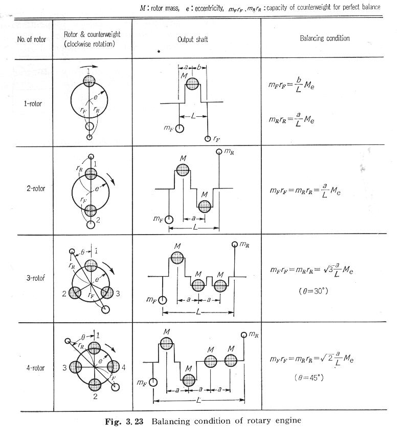
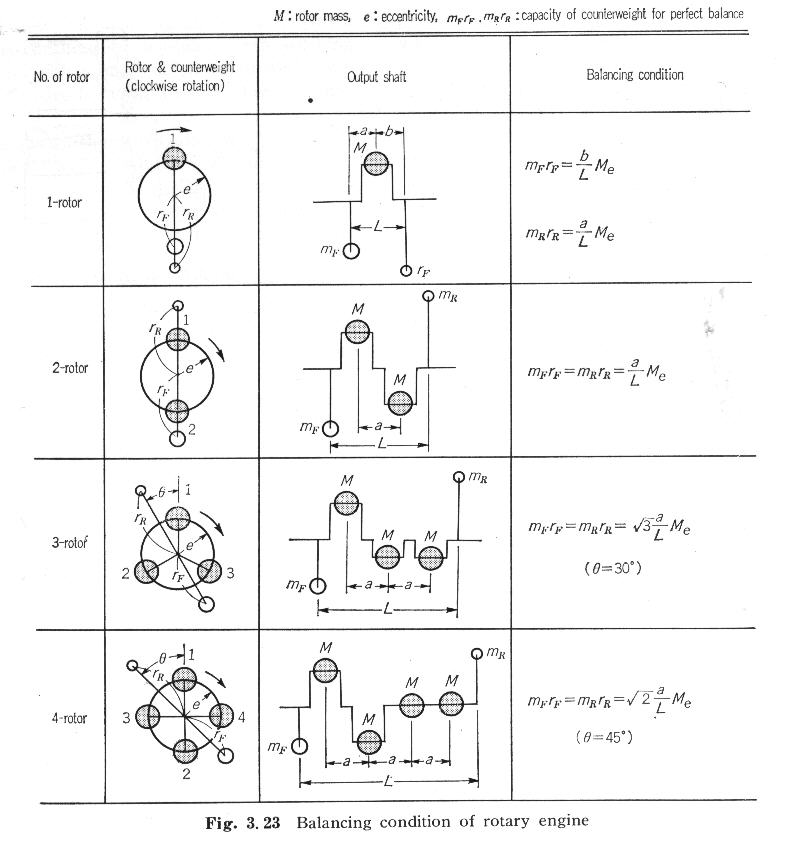
In a two and four rotor configuration the lobes would be placed at 0
and 180
degrees.
In a three rotor configuration the lobes would be placed 120 degrees
apart..
Kenneth McKenzie
Why are 4 rotor lobes placed at 0 and 180deg? I would have guessed they
would be set every 90deg...
Matt-
They are :)
Paul Lamar ...No rotor no motor.
The Rotary Engine NewsLetter. Powered by Linux.
ACRE NL web site.
http://www.rotaryeng.net
Copyright 1998-2006 All world wide rights reserved.