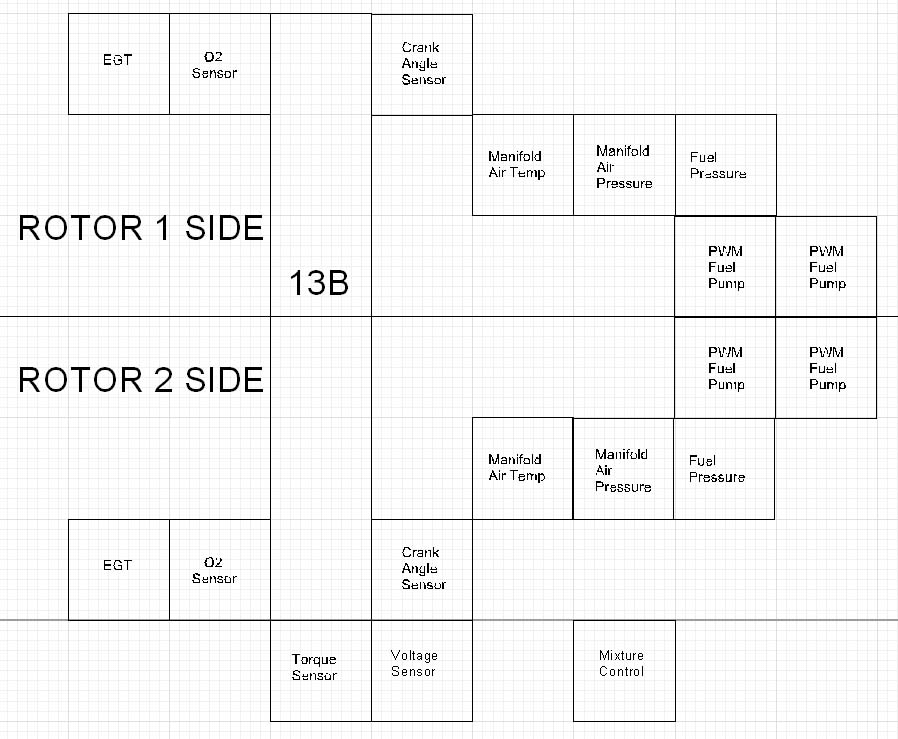
Attached is the Input-Output block diagram for the simple EFI system.
This diagram is intended to discover any missing sensors or engine
outputs (i.e., other than for pilot information).
Please comment, especially omissions. I would rather provide for a
sensor up front rather than have to patch or edit the code later on. I
realize that not everyone will want all the sensors.
Fuel flow can be calculated from the fuel pressure given a calibrated
hole in the slide throttle. The two pumps on each side (tank?) can be
operated in parallel, i.e., both on all the time; in the event one
fails, the uC can notify the pilot and increase the duty cycle of the
remaining good pump in order to maintain proper fuel pressure. Or, a
switch could be provided for the pilot to switch to the other pump.
Builders choice.
The uC system will have total redundancy a la Tracy, i.e., an A uC and
a
B uC. If one fails, switch to the other and land.
Doc Custer
Retired Software Engineer and sometime Audiologist
-----------------------------------------------------
Looks OK to me Doc. I am glad you did that diagram.
I am thinking out loud now.
You can get fuel flow from the pulse width you are feeding the pumps.
It must be calibrated because all pumps do not in general
pump an amount of fuel directly proportional (in a linear manner)
as a function of the the pulse width. Even tho the average voltage
applied to the pump is directly proportional to the pulse width.
In other words applying a 50% wide pulse to a 12 volt
pump is the same thing as applying 6 volts DC. In any event
you may need a voltage regulator on the 12V supply. If the battery
is 14 volts the pump gets 7 volts.
Another way of doing it is feeding the battery voltage to a 1/3
divider
and feed the output of the divider to one of the A to Ds in the
chip so the computer knows the battery voltage at all times.
It then uses a look up table to adjust the fuel pump pulse width
according to the available battery voltage.
This is the cheap
way to do it as you don't need a high power voltage regulator
on the 12 volt supply. If the battery voltage is low you widen
the pulse to compensate. Pumps can take up to 7 or 10 amps and as far
as I know there are no single chips regulators that will handle
that. Well at least the last time I looked. In any event you can
display the battery voltage on the instrument panel as a trouble
shooting aid.
The other possibility is to ignore the voltage level as most
alternators have a regulator that is pretty much set to 13.5 or 14
volts or so. Assume that will always put you in the mixture ball
park and the pilot in the loop will fine tune with the leaning knob.
The EGT is a bit hard to use as a feed back sensor as the response
time is very slow and
it changes direction as you pass through peak EGT. You are better off
with the O2 sensor IMHO if you are looking for a closed loop system.
I would forget the closed loop and keep the pilot in the leaning
loop. The engine will run over a wide mixture range. 10:1 to 20:1.
Air/fuel.
EGT rises as you lean the mixture and then drops as the mixture
gets leaner and leaner past peak. A tough nut to crack as far as
programming is concerned. You can lean the mixture and see if it
rises. If it rises you are on the rich side of peak EGT. If it lowers
you are on the lean side of peak EGT. This takes a lot of time
in addition to the slow response of the TC. .
the only way to speed up the response of a thermal couple is
use a smaller one. That has life limit implications.
--
Paul Lamar ...No rotor no motor.
I thought of a way to handle the EGT issue a while back.. If running
auto fuel or 100LL+TCP, include a cheap narrow band O2 sensor to know
which side of stoich you are on and then use the EGT to set the mixture
from there. The programming gets much simpler then. The only remaining
problem I can think of is that as you change manifold pressure peak EGT
changes - at lower mp, there's less total energy in the exhaust stream,
at max boost there's more.
I think the computer would have to either use a lookup table to guess
what peak EGT is at the current m.p.-rpm operating point (probably
close enough) or periodically cycle the mixture to stoich so that it
knows what the peak temp actually is. I'd prefer the lookup table method.
I'd still have a mixture control.. But instead of it directly
controlling fuel flow it would control how far from peak EGT you are,
lean or rich. Set the mixture knob straight up gets you max power
(50deg ROP), left is even more ROP, slightly to the right of straigth up
is peak, further to the right is LOP. As you climb and descend the
computer keeps the fuel flow where it needs to be to keep that
relationship.
Using the computer to accomplish this is nice because on the LOP side
the engine response curve is a much different shape (temp/power vs fuel
flow) than on the ROP side. The control is very sensitive on the LOP
side - temp/power drop quickly for a small change in fuel flow. On the
ROP side the curve is much flatter. A mechanical mixture control while
LOP is always so twitchy that managing it precisely is annoying. A good
job for a computer.
The mixture feature is less important on a turbocharged engine which can
maintain constant MP over most altitudes...
Matt-
Thanks Paul & Matt for the valuable suggestions!
Attached is an updated diagram with the changes you suggested. Notice the
voltage sensor and the mixture control.
Anybody have a recommendation for "a cheap narrow band O2 sensor?"
Experience from the field is much more valuable than a catalog.
Parts recommendations for all the sensors and actuators is greatly
appreciated! Saves me a lot of time and results in superior choices.
Doc Custer
Retired Software Engineer and sometime Audiologist
The Rotary Engine NewsLetter. Powered by Linux.
ACRE NL web site.
http://www.rotaryeng.net
Copyright 1998-2006 All world wide rights reserved.