> > Doc,
> > I just remembered I had this. No real need to run
> OBD II
> > test on the RX8 engine.
> > This will put us in the ball park.
> >
> > --
> > Paul Lamar ...No rotor no motor.
>
> Good! Adjust pump PWM to achieve fuel flow of ~1.5
> L/hr and adjust throttle
> to stoichiometric air input. Tweak as required.
>
> Doc Custer
> Retired Software Engineer and sometime Audiologist
>
> YES! You got it Doc. I am impressed.
> That came from a Mazda SAE paper on the RX8.
>
> Paul Lamar ...No rotor no motor.
You're losing some of us illterate computer types.
What is "pump PWM"???? Karibian
The RPM of DC electric motors is directly proportional to
the voltage applied to the motor.
PWM stands for Pulse Width Modulation.
It is a method of controlling the speed of DC electric motors
by switching the power on and off rapidly. If the power is on 50%
of the time the average voltage the DC motor sees is 50% of the
supply voltage so the motor runs at half maximum RPM.
It is done electronically at hundreds of times per second so
the rotating inertia of the motor armature keeps it running at
a constant speed.
The one thing you have to have is a fuel pump. So we are
making it do two jobs. Pump fuel and control the amount of
fuel the engine needs at any engine RPM and prop load.
This mostly does away with all other parts of a typical EFI
fuel system. If they are not there they can't fail.
For way more than you really need to know:
http://en.wikipedia.org/wiki/Pulse-width_modulation
<http://en.wikipedia.org/wiki/Pulse-width_modulation>
Paul Lamar ...No rotor no motor.
To amplify a bit...
Pulse width modulation (PWM) is nice for other reasons too. It would be
possible to use semiconductor circuits to regulate (linear) the voltage
delivered to a motor (or other application).. But, that would basically
mean that the regulator is behaving as a smart variable resistor. As
demand goes up, the equivalent resistance is made to go down (allowing
more watts to the device being controlled), as demand goes down,
resistance goes up - fewer watts delivered. The problem with doing this
is that system power consumed is higher, and worse yet, all of the
regulator drop is burned up in heat - the regulator has to be able to
dissipate this heat - a definite challenge. The worst point for heating
is when at middle output levels. Max and min power are fine as the
regulator is essentially not impeding current (max) or is nearly turned off.
Here's where PWM is elegant. The regulator circuitry can consume much
less power - it's either "off" or it's "on", and spends very little of
it's operating time in the middle - FET's do have transition time, but
at a reasonable switching frequency the transition time compared to "on"
and "off" time is low. PWM regulators can be very small and very
lightweight if designed properly.
Paul said that motor armature inertia keeps the motor going while the
power's off. That's true, but there are electrical effects too. Motors
are fairly inductive loads - lots of wraps of wire = big b-field.
Inductors have slow changes in current (di/dt is small). So switching
the voltage on and off quickly doesn't change motor current quickly.
You can run a PWM controlled DC motor rather slowly because of this
effect - think cordless drill.
There are downsides.. One downside is that when driving an inductive
load, the turning power off quickly portion of the cycle can cause a
high voltage across the switch. This high voltage may damage the switch
if a "flyback" diode isn't included in the circuit. The flyback shorts
the inductive kick and keeps the motor from damaging the switch.
Another downside of PWM is noise. All of that high power electrical
switching makes electrical noise - mostly conducted back through the
power supply. Running separate ground and power wires from the battery
to the motor controller might be required, and possibly a bypass cap at
the input the regulator, and maybe another one that the pump can
alleviate some noise.
The other way to deal with noise is to just live with it, but adjust the
operating frequency of the regulator so that the noise doesn't interfere
with anything else on the plane. If possible either set the operating
frequency below 30Hz - essentially inaudible, or above 15kHz (also
essentially inaudible). The pump may not run very well at light duty
cycles at the really low frequency - might physically vibrate. At
higher frequency, the noise might interfere with electronic devices in
the airplane. Plus, the efficiency of the controller probably won't be
as good as frequency goes up - more cycles/second means comparatively
more time spent with the regulator operating in a resistive range = more
waste heat.
Hopefully that was somewhat interesting..
Regards,
Matt-
That was very good explanation of linear regulator
verses PWM regulators Matt. Thanks.
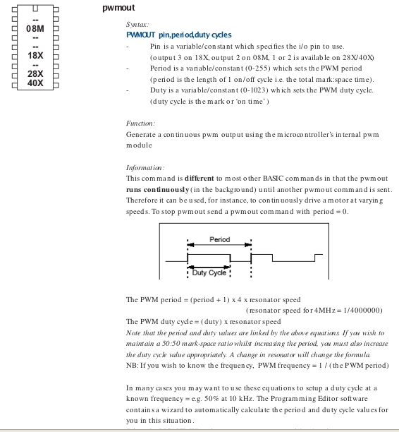
BTW this PICAXE BASIC is an amazing hardware controller language.
It is possible to set up a pulse width with one instruction
and have the program go away and do something else while the
hardware cranks out the same pulse width until it comes time to
change it. Just wonderful for our use as a super simple and super
cheap electronic fuel injection. Here is a screen capture of
the BASIC command. The more I learn about this the better it
gets.
--
Paul Lamar ...No rotor no motor.
The Rotary Engine NewsLetter. Powered by Linux.
ACRE NL web site.
http://www.rotaryeng.net
Copyright 1998-2006 All world wide rights reserved.