My grandson and I found ourselves in Pueblo with a few minutes to spare
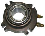
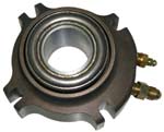
so we went into one of our favorite auto parts stores to see if we could
get a "a manual transmission clutch throw out system" thinggy. We told
the counter man what we were doing, and he produced a part, that
probably had an annular piston in it. Price was $100. Since I had no
idea what ID is required, we declined to purchase it.
Which brings to mind a whole bunch of questions, most of which can be
summed up as: What are the critical design criteria for the adaptation
of an automotive clutch throw out for use as a torque meter?
Let me check my understanding by trying to supply some of those
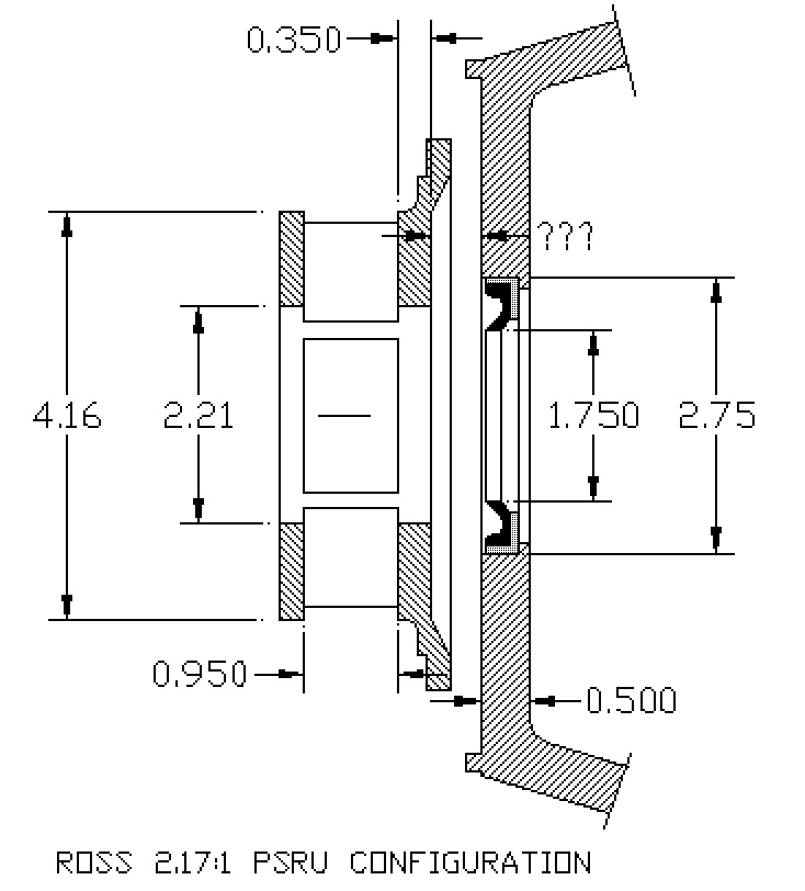
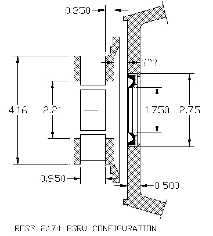
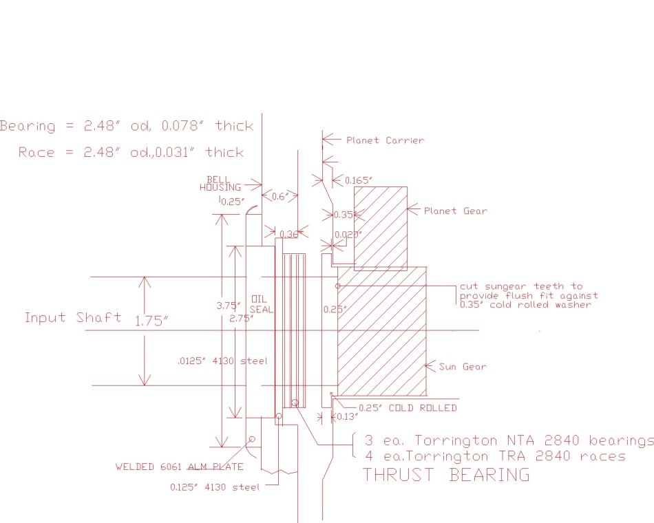
parameters. Referring to your drawing of 11/11/2001, the following seem
to be the requirements.
1. The annular piston ID must be slightly larger than the engine shaft
OD. (How much larger?)
2. The annular piston must be in contact with Tracy's existing roller
thrust bearing.
3. The new adapter must hold the annular piston in place while allowing
it to move parallel to the engine shaft axis and still provide an oil
seal. (I expect that the movement is minimal.)
4. The new adapter must hold an oil seal in position to prevent oil from
leaking around the engine shaft. What is the range of pressures? Is this
the engine oil pressure?
5. The new adapter must provide a chamber for the pressure transmitting
fluid.
6. The new adapter must provide a place to mount a pressure sensor or
tube to a gage in contact with the fluid.
7. The new adapter must provide a way to purge all air from the chamber
holding the pressure transmitting fluid.
8. The new adapter must be strong and robust enough to deal with the
entire thrust transmitted to it by Tracy's thrust bearing. How much thrust?
So, it would appear that the only piece usable from the automotive
clutch throw out mechanism is the annular piston.
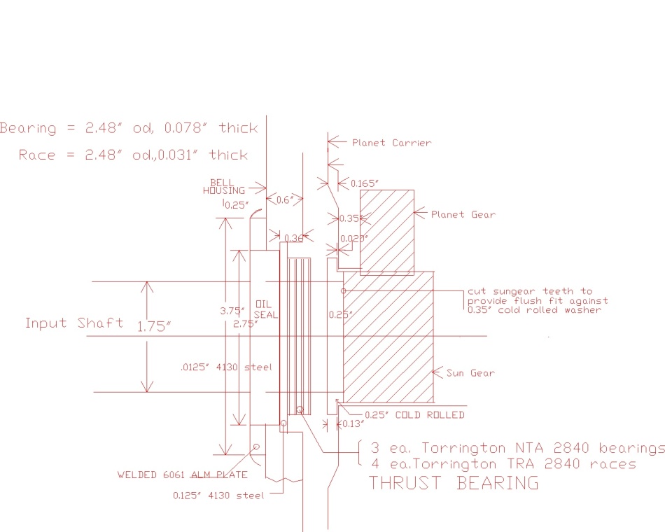
There seems to be an assumption regarding the fit of Tracy's roller
thrust bearing and the engine shaft. That assumption is that the thrust
bearing is free to move along the engine shaft. Is this true?
Rather than a hose to a gage on the instrument panel, I would suggest a
pressure sensor embedded or screwed into the adapter that would provide
an electronic output.
Presumably the volume behind the annular piston is filled with a fluid
of some kind. This means there must be some way of bleeding the air from
the system.
Is brake fluid an acceptable pressure transmitting fluid? Is there
something better?
What kind of access, if any, is necessary for servicing?
Doc Custer
Retired Software Engineer and sometime Audiologist
Answers:
1. .005"
2. True. Some units may have a ball thrust bearing built
in.
3. True.
4. Depends on the area of the annular piston. It has nothing
to do with the engine oil pressure. An entirely separate system.
5. True.
6. True.
7. True
8. See the attached pdf file.
The Howe Racing unit should work as is. You might need a
bushing to reduce the ID or mount it in a large cup shaped
adapter in the large 1/2 inch thick adapter plate
on the torque isolator side.
Yes the thrust bearing and sun gear is free to move slightly.
Paul Lamar ...No rotor no motor.
The Rotary Engine NewsLetter. Powered by Linux.
ACRE NL web site.
http://www.rotaryeng.net
Copyright 1998-2006 All world wide rights reserved.