>
> Paul,
>
> I have explored a few VGT turbines now and we need to have a ball
> park idea
> of how much torque can the turbocompound turbine technique tweak.
>
> Say that phrase 5 times and you will have an idea of my
> frustration
> level:)
>
> To deliver 54 Hp net to the e-shaft we would like to have about 4
> ft/lbs of
> torque at the turbine output at 80k rpm.
>
> Said in another way, to produce 4 lbs of torque at 80,000 rpms
> a TE-04
> turbine would have to output about 61 Hp output. Likely? The torque
> on the
> three inch turbine tips would be what about 12 ft/lbs
>
> Said another way a compressor attached to this turbine in
> operation is
> unlikely to requiring 61 Hp to perform its function of compressing
> air for
> the engine. Logic would suggest we need a bigger turbine. How big?
> If it is a blow down impulse style Gordon has already shown how it
> would be
> over three feet in diameter.
>
> We are planning to use a more efficient reactive turbine with VGT
> technology.
>
> Reeves if you get this thread could you give us a ball park figure
> on the
> torque or Hp output of any turbine in the TE-04 or TE-06 class
> you have
> experience with testing? Assume 80K rpm. operational speed.
>
> Obviously there are a lot of turbines out there to choose from but
> if their
> output is only .1 ft/lbs to 1 ft/lb then we have to seriously
> reexamine our
> turbo compounding.
>
> Best Regards
>
>
> ...snip...
Doug,
In order to determine how much power a given turbine will absorb, we
have to think in terms of momentum. Just as momentum theory can tell
us how much thrust a propeller of a given size can produce if we put
a given amount of power into it, so momentum theory can tell us how
much power a turbine impeller can absorb if we put a given amount of
thrust into it -- thrust being the blowing of the exhaust jet.
Momentum is simply mass times velocity. When you take the exhaust
jet from a rotary engine and direct it at a turbine wheel, the
turbine wheel will convert some of that momentum into a force, which
is change of momentum over time. The turbine wheel will accelerate
as a result of the force imparted by the change in momentum.
How much force? In order to figure that out we need to know the mass
and velocity that makes up our momentum. So we need to know the
velocity of the exhaust gas, its density and the area of its
streamtube or duct.
Remember the general thrust equation?
Force = (mass flow * exit velocity) - (mass flow * freestream velocity)
This tells us how much force we can make by accelerating a given
mass of air to a speed that is faster than the surrounding air.
In order to figure out how much power a turbine can absorb, we
simply turn this equation around:
F = 2 * mass flow ( V entrance - V exit)
To figure out torque we multiply force times the radius of the
wheel: T = FD/2
From there we get power by multiplying by rpm.
Ahh, but things are not so simple. What we just did is valid for an
impulse turbine where the momentum change occurs as a result of the
fluid hitting a bucket and imparting its energy to it directly. This
is analogous to the thrust of a jet engine hitting the air and
accelerating the airplane as a result.
But a reaction turbine is different. The momentum is imparted to the
wheel not as a result of a direct force hitting it (like a jet
engine), but as a result of a pressure change -- just like a
propeller creates thrust by virtue of a pressure change in front of
and behind its airfoil-shaped blades.
Fortunately we can modify our general thrust equation to accomodate
this twist -- simply by bringing in good old Bernoulli:
Remember our general thrust equation?
Force = (mass flow * exit velocity) - (mass flow * freestream velocity)
But our propeller creates thrust as a result of a change in pressure so:
F = Area * delta Pressure
What we end up with is:
F = 0.5 * density * Area * (exit velocity^2 - freestream velocity^2)
So looking at this we see that if we know the density of the air,
the area of the propeller, the exit velocity of the propeller
streamtube and the freestream velocity -- which is the flying speed
of the airplane -- we can figure out the thrust that the prop is making.
Again, we can turn this around to figure out the amount of force
that an impeller is absorbing if we blow air through it, such as
with your recovery turbine.
Here is a link to an article that will help:
http://www.du.edu/~jcalvert/tech/fluids/turbine.htm
We can see, however, that in order to make the calculations we need
to know the exhaust gas mass flow, which is made up of its density,
its velocity and the area of its stream or duct. We also need to
know the velocity of the gas after it leaves the turbine, which is
going to be the hard part, I believe.
We also need some idea of the turbine blade geometry because the
analysis relies on vector triangles.
Regards,
Gordon.
\\
Gordon,
Thanks for the clear explanation. In seems we are still lacking like
you said the velocity of the gas which is only an estimate based on how
it sounds at the moment. I still believe we have to speak with someone
who has experience with turbine dynoing. So far I have only found
companies doing that with large jet turbines. Reason would have it that
Garrett would have such equipment though.
Sorry for the brief note. I am in Germany at a technical training
now playing with inverters and remote alternative energy grid design.
I'll be back home on Monday.
Cheers
Doug
Hey Doug,
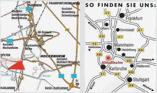
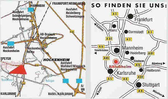
Get down to Altlussheim/Hockenheim Haupstrassa 154
Phone 062 05-307661 and go to the Wankel Museum. Well worth
the time.
www.autovision-tradition.de
Attached is a map.
Paul Lamar
The Rotary Engine NewsLetter. Powered by Linux.
ACRE NL web site.
http://www.rotaryeng.net
Copyright 1998-2006 All world wide rights reserved.