Here are the essentials.
--
Paul Lamar ...No rotor no motor.
Paul,
How would you purge air out of the system in this
arrangement? I know
that this has been discussed in detail in the past, but it
seems that
you would need a line from the rear side housing to the
pressure can in
order to purge air that may be trapped in the engine.
Mark S.
You must run a vent line from the highest point in the
system
to the top of the pressure can. In a tractor tail
dragger it
would be
the rear (car) end housing. The housing closest to the
PSRU.
The best place is where you have the pressure fitting now.
I think
it is the return line from the water heater port in the
stock
RX7 system.
The pressure container must be mounted as high as possible.
The cooling system is constantly generating tiny steam
bubbles. These must be able to rise to the highest point in
the
system which should be just below the pressure cap.
When the
pressure
in the system rises to the blow off setting of the
pressure cap
this steam accumulation will be the first thing purged to
the catch
can.
Paul Lamar ...No rotor no motor.
Paul,
Yes, wp-plumbing5.jpg shows it more clearly. I didn't see that
line in
the previous jpg.
On my installation, the radiator is angled from front (highest)
to rear
(lowest), so I have a 1/4" line going from the upper most tank
back to
the pressure/swirl tank.
One caveat, when filling the cooling system, it is possible
(likely) to
get an air pocket in the vicinity of the wp impeller. In my
installation (20B, thermostats removed), running the engine
will
not purge the air from this area. You must remove a plug from
the side
of the wp housing and continue adding coolant until liquid runs
out the
hole. Then replace the plug, run engine and coolant should
circulate.
An easy way to tell if it is circulating is to hold your
hand on the
outlet from the wp after the engine has been running for a
minute or
two. If it is warm/hot, water is circulating. If it is
still cold,
there is no circulation. It is my understanding that more
than one
engine, following rebuild, has been fried due to this
scenario. It may
not be a bad idea to install a petcock on the side of the wp
housing
for
the purpose of purging air when refilling the cooling system.
Mark S.
Instead of reinstalling a plug in the side of the wp housing,
would it
be worthwhile to run a purge line from there to a high point in the
system? I guess it might depend on how tough the plug is to get
to once
everything is installed on the engine..
Matt-
Here are some water pump pictures. Perhaps Mark S can mark
them up using MS paint for us. The 13B Cosmo pump and the 3 rotor
pump are the same. Note the bleed hole at the top of the
pump cavity.
Paul
Paul,
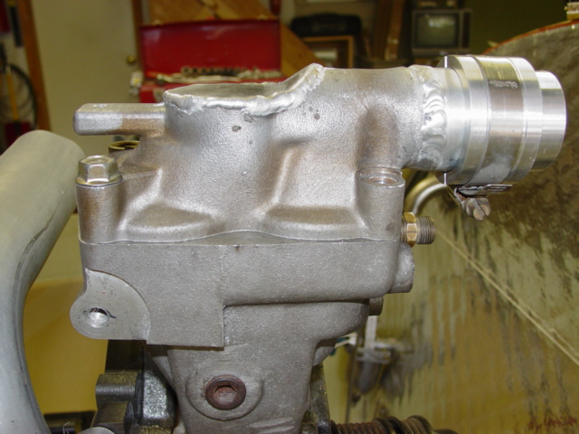
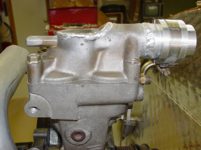
Here's a picture of my water pump housing. There's a plug in the side
that I now use for a pressure sensor. I remove the pressure sensor when
refilling the cooling system. I add coolant until it starts coming out
the plug hole, then I replace the sensor and continue filling. My wp
housing does not have the bleed hole as shown in
Bulents_Cosmo_pump2.jpg. Did it come that way or did he add that?
I've resisted adding a purge line as it is an additional failure
point. A petcock or Schrader valve would be preferrable.
Mark S.
I don't recall Bulents pump having that feature.
Bulent's pump had the bleed hole as stock.
What did you do about the bypass?
I see you are using the Wiggins couplings. Nice work!
--
Paul Lamar ...No rotor no motor.
Paul,
Thanks. Maybe its time to discuss the "wiggins" type couplings again
for the benefit of all the new folks on the ACRE. Personally, I love
their elegant simplicity and the fact that it enables me to use aluminum
tubing throughout the system. I have a bag of spare o-rings so I can
replace the old o-rings whenever I open the system. They look very
high-tech and you don't have to worry about them slipping off. It does
require more time with the initial fabrication (tig welding), but once
they're fabricated, they should last forever. As for the tig
welding, they are easily welded to the aluminum Mazda water pump
castings. Great little devices.
Mark S.
The Rotary Engine NewsLetter. Powered by Linux.
ACRE NL web site.
http://www.rotaryeng.net
Copyright 1998-2006 All world wide rights reserved.