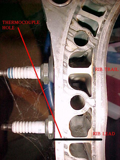
> I think the cylinder heat temperature thermal couple
will also
> be a key component. I am very excited about Mark S's
installation
> of CHT probes in his 3 rotor. This area is immediately
adjacent
> to the spark plug.
>
> BTW Mark, I will drop off the 2, four channel data acq
modules
> when
> I'll see you a week from this coming Sunday.
----------------------------------------------------------
> Paul Lamar
>
>
> Paul, Mark
>
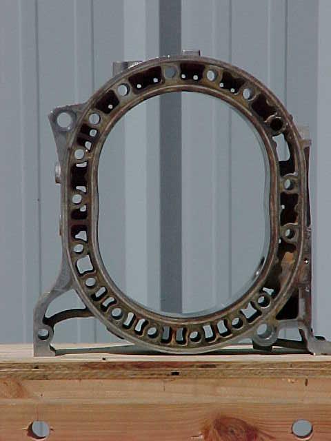
> I'm curious about Mark's installation of thermocouples
as shown
> in the
> photos. Will there be trouble with electromagnetic
interference
> from
> the the plug/plug wires? I know the wiring will be
shielded, but
> am
> curious as to what type/class of shielding will he use? Also
> what type
> of T/C and range and or part number. Thanks.
>
> Allen
> Houston
----------------------------------------------------------
> That is something I hadn't heard of. The CHT probes are real
> close
> to the plug wires in my O-470 and that does not appear
to be
> a problem. On the other hand they and the spark plug
wires are
> shielded. I guess it is possible. If we sample the data
often
> enough the spark will appear in the data at idle.
>
> Have you experienced RF interference with thermocouples?
>
> I'll let Mark answer the last questions as I don't know
> what he used.
>
> Paul Lamar ...No rotor no motor.
-------------------------------------------
> Hi Allen,
>
> I used regular unshielded thermocouple wire and quality
> automotive
> silicone plug wires. I'm using Tracy's EC-2 and EM-2. So
far,
> the CHT
> readings are rock steady, so I would conclude that
interference
> isn't a
> problem. That could change with the data loggers, but
I'll have
> to wait
> and see.
>
> Mark S.
-------------------------------------------------------
> Mark,
>
> Would you mind telling me what kind of T/C's you are
using? I'm an
> instrument engineer that works in the oil/gas industry and it's
> standard
> that T/C's have shielded wire so they won't pick up any stray
> voltage.
> Are your thermocouples milivoltage types, say like a Type J,
or some
> other range? Are they grounded tips? I'm just curious as I
know the
> plug/plug wires do put out some high voltage (although I'm
am only a
> neophyte when it comes to engines and aircraft).
>
> Allen
> Houston
-----------------------------------------------------------
> Allen,
> It is either type J or type K, don't recall. It takes one type
for the
> cht and the other for the egt. I bought the wire, stripped and
wrapped
> the ends, then melted the ends with a tig welder. The TC wire
> is 2-wire, covered in some medium brown cloth looking
insulation. I
> didn't see any shielding. The exhaust TC's were purchased
from ACS.
> They are the type with the nut that screws onto a welded
bung. Those
> have shielding on them, but only for about 12" to whree the ring
> terminals are located. I just assumed the shielding was there to
> protect the wire from the hot exhaust pipes.
>
> Mark S.
-------------------------------------------------
Mark,
The shielding on millivolt and milliamp wiring is either terminated at
the device end or the "control" end (reading end) of the circuit but
not both OR neither, and it should be connected to the ground bus or
terminal(s). The shielding should be "continuous" from probe to your
reading device/control device. There is a quick treatise on:
http://www.omega.com/prodinfo/Thermocouples.html
What size was the hole you drilled (diameter) for the thermocouple you
inserted? I think that's pretty cool that you made your own by welding
the bi-metal wiring together. Never heard of anyone doing that.
Allen
Allen,
There is a metal tip that fits into the exhaust header that the
shield is attached. I never really thought much about it, but I
imagine that provides the ground for the shield (from the exhaust
system to the engine block and then to ground).
As for welding the ends of the TC wire for the CHT probes, I believe
I got that idea from Tracy Crook. I'm not sure he suggested using a
TIG welder, but the idea was the same. Worked great (price was
right too). So, should the tc leads be shielded?
The holes were pretty small, just big enough to push the TC wires
into. The pictures of the housings are a little deceiving in that
the web is narrowest out near the edge and gets thicker the closer
you get to the spark plug. There really is quite a wide area to
drill into at the spot where you need to drill. Just remember to
stop drilling when you hit the steel liner.
Mark S.
The Rotary Engine NewsLetter. Powered by Linux.
ACRE NL web site.
http://www.rotaryeng.net <http://www.rotaryeng.net>
Copyright 1998-2006 All world wide rights reserved.