Paul,
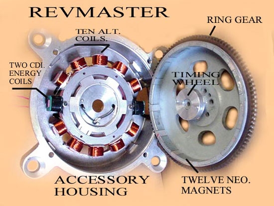
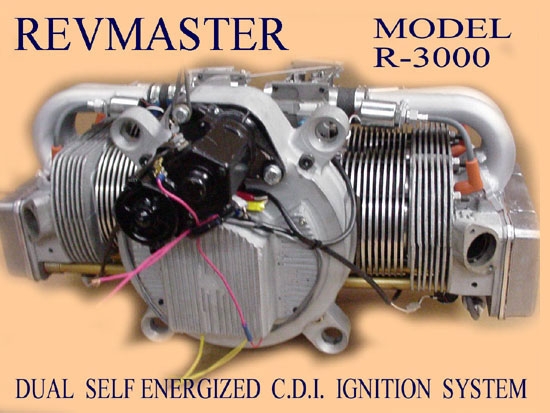
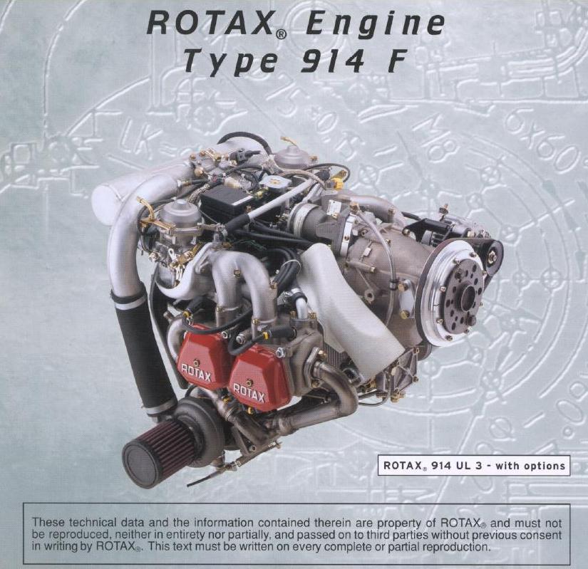
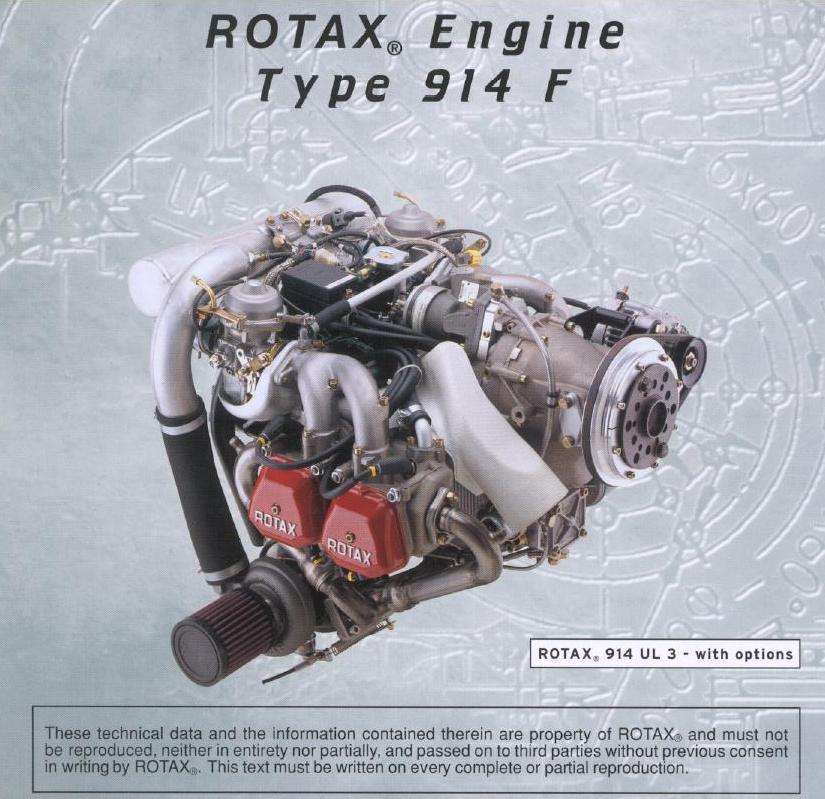
Here is my idea for the flywheel magneto. It is based on the Rotax
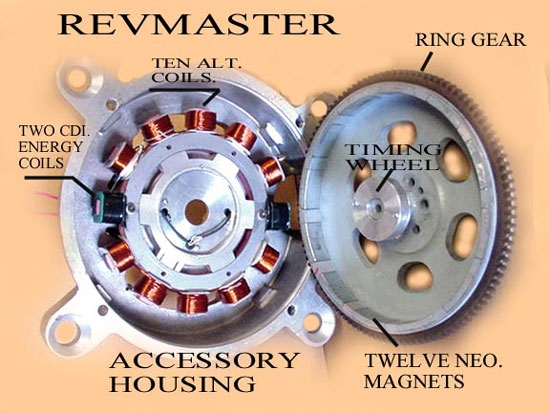
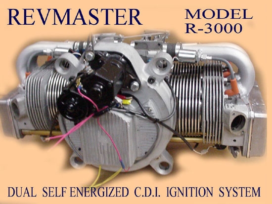
scheme -- also used by Revmaster and others, including continental with
its IO-200 experimental engine. This is also used on your lawn tractor
if it has electrical system, motorcycles and all kinds of other
applications.
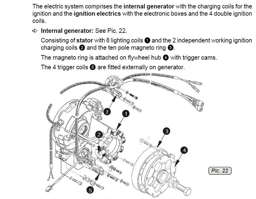
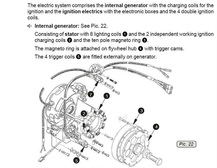
The first drawing (picture 22) is from the Rotax 914 manual and shows
the exploded view of the system, which mounts to the back of the engine
on the accessory side. This is where I would put it on the rotary too.
You can see the stator ring and the coils. it uses ten coils total, two
of which supply juice to the ignition, the rest go through a rectifier
and supply 20 amps for airplane electrical.
I would use 12 coils, 30 degrees apart -- provided the stator would be
small enough to fit and not interfere with the water pump. If that won't
fit, I would find a small unit from a motorcycle wiht fewer coils that
is sure to fit.
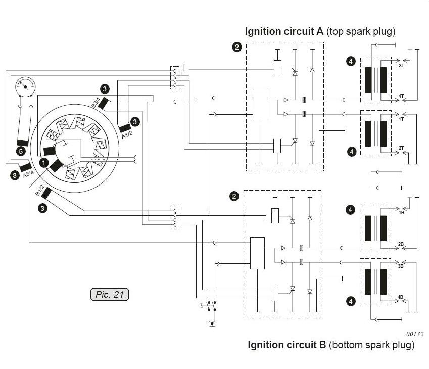
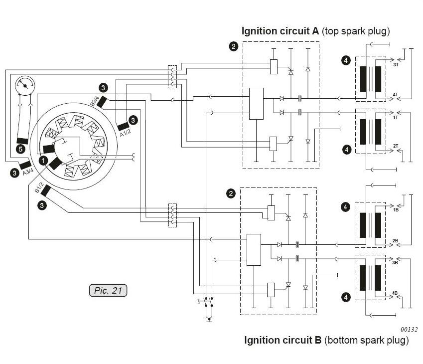
Picture 21 shows the wiring schematic. You can see that there are two
charging coils for the ignition. I would use four coils for the
ignition, one for each spark plug.
You can see that there are five magnetic pickups on the outside -- four
for the wasted spark ignition and one for rev counter. I would use four
sets of points instead, one set for each spark plug.
The points would be mounted on the outdie and the rotating cover plate
would have small bumps attached to actuate the points. The current would
go from each of the four ignition stator coils to the points and then
from there to the high-output coil for each spark plug.
The current from the stator coils would be going into the primary
windings of the spark plug coil for as long as the points are closed,
which is the majority of the revolution. When the points are bumped
open, the primary magnetic field collapses, triggereing the high-voltage
secondary juice to the plug.
There is no need for capacitor discharge because the spark energy will
be very high at high rpm. (The faster the magnets in the flywheel spin
past the coils, the greater the electrical potential and thus voltage to
the primary side of the spark coil -- probably hotter than most CDI
systems).
Also since there is a set of points for each spark plug, the dwell time
will be close to 360 degrees, ensuring that the coil primary has lots of
time to charge up, even at very high rpm, where each cycle is only a few
milliseconds.
So what you have basically is a magneto with four independent ignitions
-- one for each spark plug. You could have a failure in any one of the
four and still keep running on both rotors.
The second, belt-driven alternator, I would mount to the front, with a
pulley on the backside of the prop flange, again like the Rotax. This
way the alternator is spinning at prop rpm instead of high engine rpm
all the time.
I will do up a proper drawing when I have some time.
Regards,
Gordon.
Mistral was going to do something like this awhile back.
I wonder what happened to that project.
Paul Lamar ...No rotor no motor.
The Rotary Engine NewsLetter. Powered by Linux.
ACRE NL web site.
http://www.rotaryeng.net
Copyright 1998-2006 All world wide rights reserved.