SCROLL DOWN
Paul,
I am a mechanical engineer that owns a cnc machine shop in northern
California. As a new pilot, and a past rotary engine builder, I am in
the progress of developing an aircraft specific rotary using some off
the shelf Mazda parts and many custom parts. The current goal is to
offer these parts to the experimental aircraft market within the next 2
years. I am estimating around 1 year of design and prototyping and a
year of endurance testing before release of any products.
The real motivation is I will be starting a Velocity XL kit this fall
(after the Reno Air Races), when my time will become a little easier. I
am the team engineer and fabricator for Team Steadfast owned by Will
Whiteside. We use a 2005 Romanian built Yak 3U with a P/W R2000 radial
engine. You can check out the web site at teamsteadfast.com.
Please add me to your newsletter mailing list. Your web site is great!
I would like to use you as a sounding board to possibly review some of
the parts we will me making on the basis you keep them confidential
until we are ready to release the parts to the market. My plan would be
to resale the parts through the existing guys building rotary aircraft
engines, as I really don't have any interest in being an engine
assembler (besides my own)!
Thanks,
Larry Childs
Designit Prototype
5935 Labath Ave
Rohnert Park, CA 94928
Cell 707-753-0702
I'll be glad to help anyway I can.
You are also just the person I have been looking for.
I have been farming prototype work out to various local NC machine shops
but I would rather keep it in the Wankel rotary community. I pay for it
out of my own pocket no problem.
I am trying to design a slide throttle low pressure fuel injection
based on the Ellison carb. We have a guy already set up to make
the slide throttle itself. I am building up a p-port RX8 engine
and we will initially run it on the Mazdatrix engine dyno with a Weber carb
to get a base line. Once that happens. I will try some of these other ideas
for
low pressure mechanical fuel injection. The traditional EFI is overkill and
too
expensive. Most people are attracted to the rotary for cost reasons.
Also it relies on a functioning electrical system which does not always
function.
This design steals ideas from Ellison and Mikuni.
The fuel metering is done with a bunch of small holes
drilled into a brass tube that stays in the air passage
all the time similar to the Ellison. As the slide opens it exposes more
and more small holes in the brass tube increasing the fuel flow.
The brass tube is attached to the spacer. The fuel comes in through the
spacer and down the column to the brass tube. The brass tube
fits in holes in the center parts of the slide. The fuel is
sucked out of the side of the tube by the Coanda effect.
Ellison claims excellent atomization.
It uses a tried and true method of metering fuel. There are
hundreds of Ellisons out there on all sorts of airplanes. The mixture
is
also leaned with the external fuel pressure regulator. The Ellison of
course has a built in fixed fuel pressure regulator.
I calculated the air opening area of the slide in .2 inch travel
increments. I then attempted to match the fuel flow to the slide
opening area.
Roughly speaking it takes 27 .013" dia. holes variably spaced
along the tube. Each hole passes enough fuel for 4.45 HP at 2 psi so
27 holes is 120 HP per runner. 240 HP for the p-port engine.
As Ben Ellison says this causes a stepped ramp digital supply of fuel.
In other words the engine goes from rich to lean and back to rich as
the slide moves. The problem is severe in the first one third
travel of the slide throttle. Ellison largely got around this by
using much smaller holes and many more of them. My guess by looking at
them is
they can be as small as .1 mm or around 6 thousands of an inch. He
probably has
close to 100 holes in his tubes.
More, much smaller holes, soon becomes a problem in a single row as
the holes get too close together. Two or more staggered rows are used
in the
Ellison. The first 3rd are a single row. The next third is a staggered
double row and the last third is a staggered triple row. None of this
is shown
on any Ellison websites. Of course this further increases the cost.
I talked to a friend of mine that owns an NC shop here in Santa
Paula that has experience drilling small holes. He says there must be
a close
fitting brass rod in the brass tube or drill breakage occurs
frequently. At
$45 a crack you don't want this to happen. Then you have the problem
of pressing
the sacrificial brass rod out of the nine inch long 1/8 inch diameter
tube.
Not an easy thing to do. That too requires special tooling that
supports
the outside of the tube. Perhaps this can be done better with a laser.
I have yet to investigate the laser option. I am sure this outfit
can do
the job. I'll know more about the cost on Monday.
http://www.calasers.com/gallery.html
Two Ellisons would work fine but at $850 each they are too expensive
for most rotary guys.
Paul Lamar ...No rotor no motor.
Paul,
Are you doing your designs in Solid Works? If so, I have the animation
package and can animate most models. On the fuel injection, I will most
likely use a redundant efi computer set up. I have extensive experience in
setting up custom computers to perform what I need. On the thought of
drilling the tubing, send me a drawing and I'll see what I can figure out.
I have several 12k rpm spindle machines, so it makes many small holes easy
and fast. And working with you on R&D, as long as I make your parts on
weekends, I don't have to charge you shop rate.
I can also give you some insight on how we build a cockpit mixture control
in an sprint car. (there are lots of racing series with "larry rules" now).
Have you cut your "P" ports yet? If not, don't as I will pass on what I am
doing. 3D machining leaves us much more opportunity to be creative in the
port shape and timing. Delaying the intake port opening timing on a pp will
help reduce overlap on a turbo normalized engine. I have a couple of car
blowers around and will use one of them to make a flow bench for rotary
work. It's really easy to tie it to a Ford 90mm mass air flow sensor to get
very accurate readings.
Thanks,
Larry
Thanks for the offer Larry. I'll take you up on it. I will need a few
parts for the RX8 p-port engine.
I do everything in Rhino but when it is headed for an NC shop I export
it to Solid Works as most NC shops can covert Solid Works to G codes.
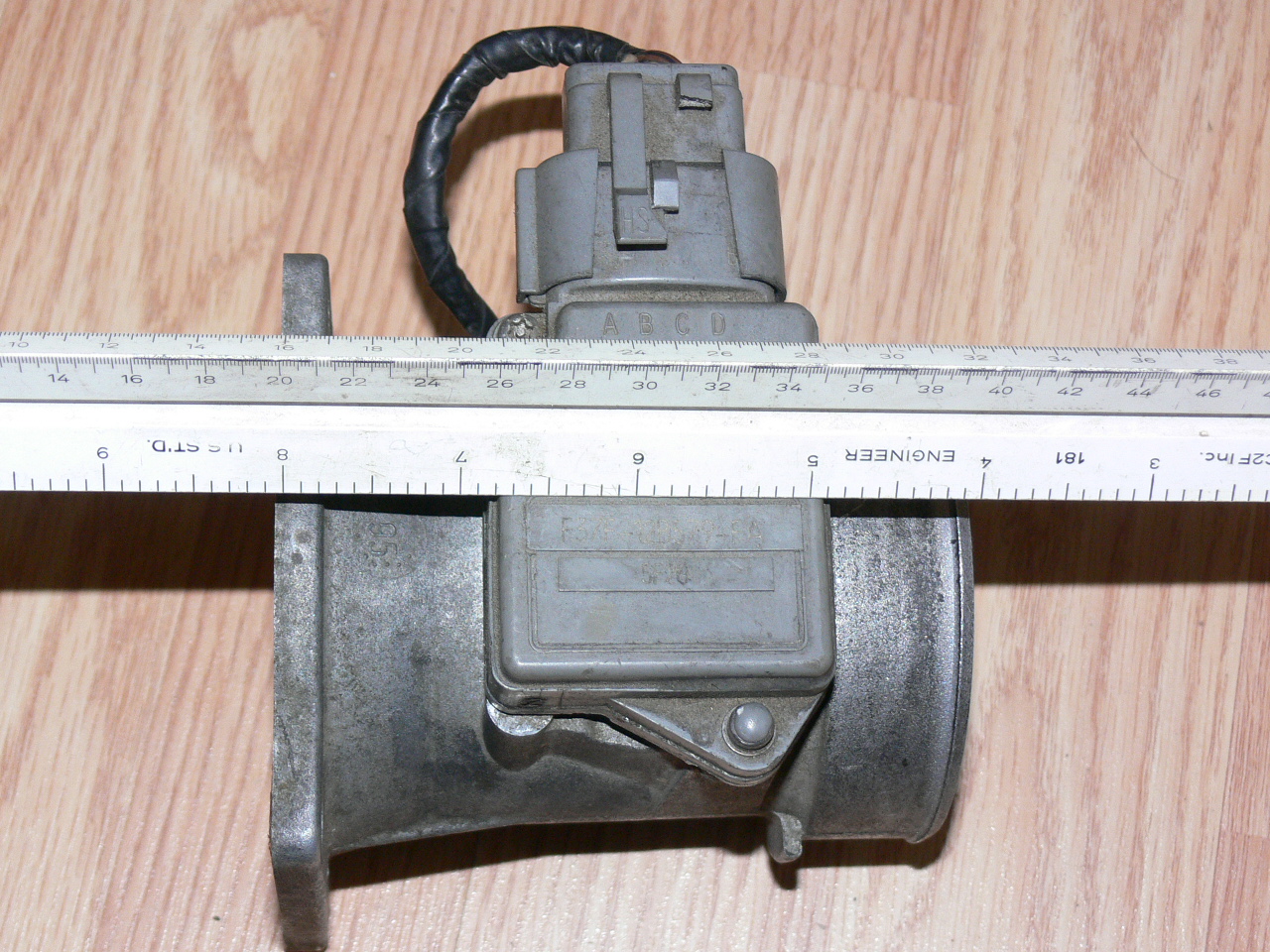
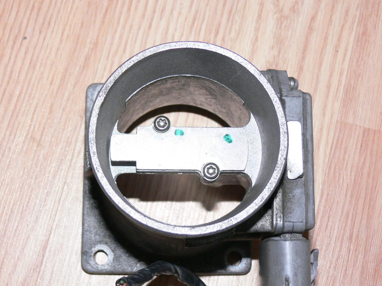
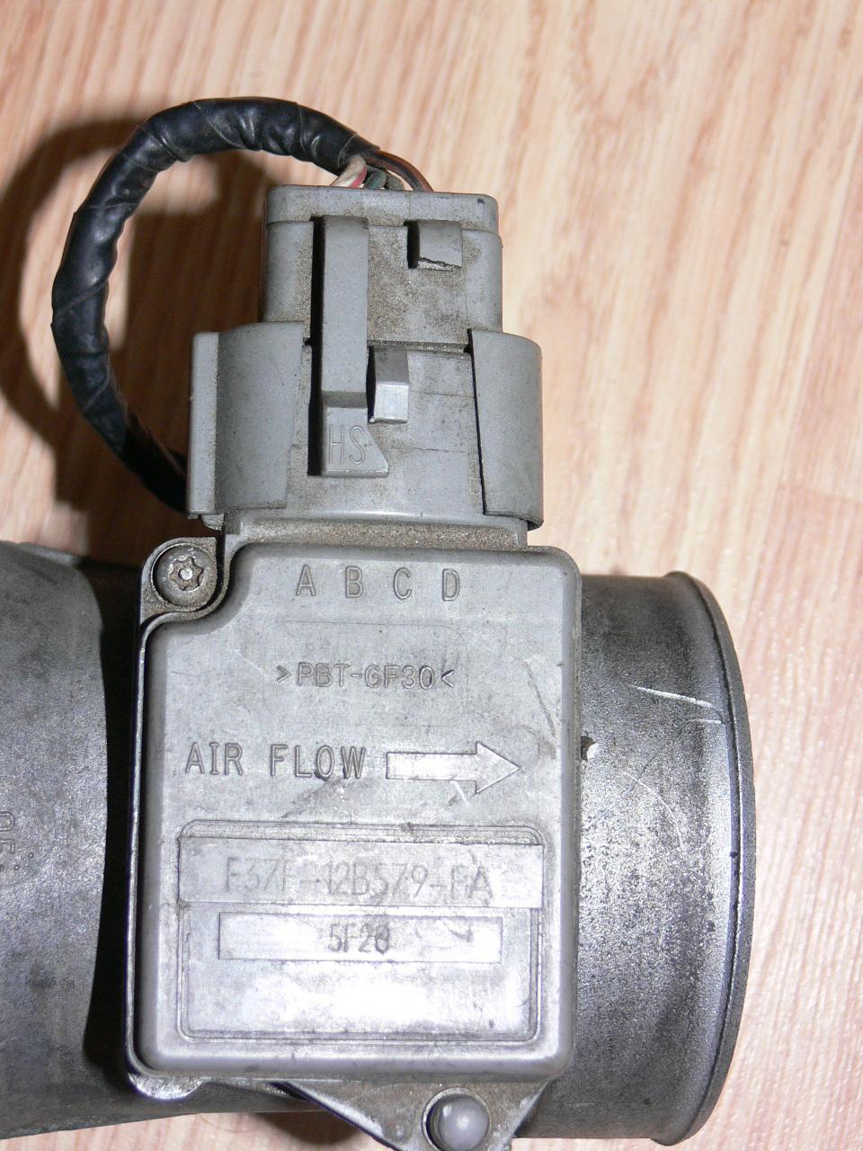
Here are some pictures of that Ford Escort mass airflow sensor I picked
up yesterday from a junkyard for $39. This is for the computer types that
want to roll their own simple PICAXE controlled PWM fuel pump systems.
Perfect between the plenum and the intake air scoop. Sounds like we are
on the same page here :)
I have not cut the RX8 ports yet. Mazdatrix is taking apart the
RX8 engine as we speak. So far we have done it in a Bridgeport with
a boring head. We got 240 HP at about 7000 RPM with a Weber 58 mm.
That was a second gen engine. 7500 RPM is our limit as the only PSRU readily
available is 2.85:1 gear ratio.
BTW in case you are unaware of this. We are now welding the .049 wall SS intake tube
to the steel liner. I'll send more pictures shortly. Turned out to be
a lot easier and better than I thought.
Paul Lamar ...No rotor no motor.
The Rotary Engine NewsLetter. Powered by Linux.
ACRE NL web site.
http://www.rotaryeng.net
Copyright 1998-2006 All world wide rights reserved.