Has anyone used the p port slide throttle with Tracy Cook's ECU?
After changing my engine to the P port configuration with the slide
throttle mounted close to the engine the ECU does not work. There is no
good pick up point for the manifold pressure sensor hose. The hose
connected between the engine and slide throttle gets the rapidly
fluctuating impulses and also fills with fuel from the injectors.
Are there any engines running with this ECU and slide throttle set up ?
John Prendergast
Mark Supinski is trying as we speak. Any day now. We had it running
on the dyno
but I ran out of dyno money before we got it tuned properly. The
engine would start easily
and run but the mixture was all over the map..pardon the pun.
Since then Tracy has changed
the computer a lot. I suspect the problem may have been >>when<<<
Tracy was sampling the
intake manifold pressure. He only takes one sample per rev so it is
only a few
microseconds long. IMHO many samples should be taken and averaged.
The same thing
might be possible by hooking up the two pressure taps, one from each
rotor,
to a vacuum can to smooth out the pulses. Slide throttles don't give
good
intake manifold pressure signals when they are wide open as there is
little
pressure loss in the intake system. That is why they make more power.
All of Tracy development has been done with a plenum on the end of
the tubes
sampling the pressure just after a single throttle body.
If your vacuum lines are filling with fuel something is wrong with where
they are mounted. We did not have that problem. Here is a picture of
our set up. Can you send some pictures of yours? Where are your
injectors located?
You can also try the apex oil injector ports in the rotor housings
for a place
to sample the intake vacuum... if any :)
Paul Lamar ...No rotor no motor.
The injectors are located in a similar position as in your pictures
except the elbows go forward and then down to clear the cowling. The
vacuum pick ups are located between the slide throttle and engine.
I believe the compression wave generated is causing the problem. The
vacuum gage shows such a rapid large fluctuation at the low rpm range
that it would destroy the gage in short order and stops fluctuating
after a short period when the hose fills w/ fuel. The ECU T's off the
same hose which of course could not function properly with these conditions.
The Slide throttle plate is so close to the engine that I believe the
pressure wave bounces off the almost closed plate causing the rapid
fluctuations and the pushing of fuel into the hose.
With the original configuration the throttle body was farther away
allowing a larger volume of air to modulate these vacuum and compression
wave pulses and the injectors were located at the engine not before the
vacuum pick up point as it is now.
John Prendergast
----------------------------------------------------------
I agree with you on the pressure waves.
Try smaller hoses feeding into a large can located some distance away.
What you are interested in is the average pressure and not the instantaneous
pressure. I am amazed the gage is responding that fast. Is it silicone
fluid filled?
What size hoses are you using now?
We used soft silicone hose which is very flexible. A restrictor in the hose will
also work. Drill a small pin sized hole through a piece of aluminum or plastic rod
that fits in the hose. You have got to get rid of those pulses
as no telling what the pressure sensor is reading as it is only
sampled for a few millionths of a second. Only Tracy knows when.
The first length of the hose could or should be larger
so capillary action of the fuel will not occur. If the hoses
are coming out of the top of the intake tubes the fuel should drain
back out no problem.
Does the hose come off the top of the tubes? We did not have trouble with
fuel in the hoses as far as I could tell.
Mark Su, Please check and see if you are getting fuel in your hoses.
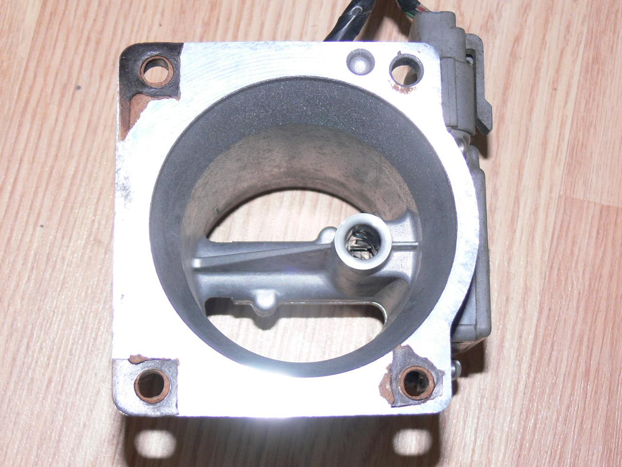
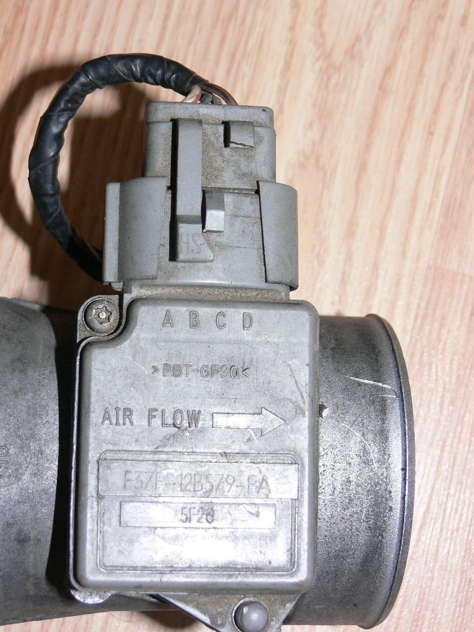
Perhaps we can talk Tracy into a mass airflow sensor mounted on the
input to the plenum. Mass air flow sensors put out a zero to
five volt signal just like the pressure sensors. However they have
a long time constant as they basically measure temperature of a hot wire
and that does not respond to rapid changes in air flow. It automatically
averages out the air flow velocity.
BTW what does your mixture look up table look like? Perhaps you can
share yours with Mark Su to get him in the ball park
as your engine is running.
Paul Lamar ...No rotor no motor.
The Rotary Engine NewsLetter. Powered by Linux.
ACRE NL web site.
http://www.rotaryeng.net
Copyright 1998-2006 All world wide rights reserved.