>
> >
> > Hey Buly, what are the dimensions of your water radiator?
> >
> > Scott Gettings
>
> I don't remember Scott, but I'll check tomorrow and let you know.
> Buly
>
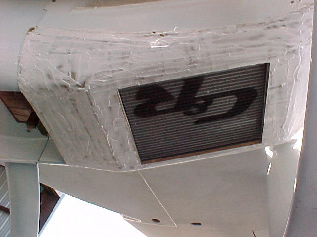
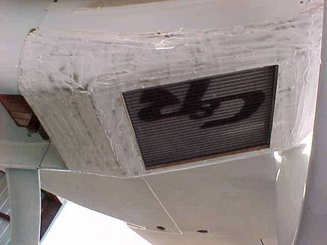
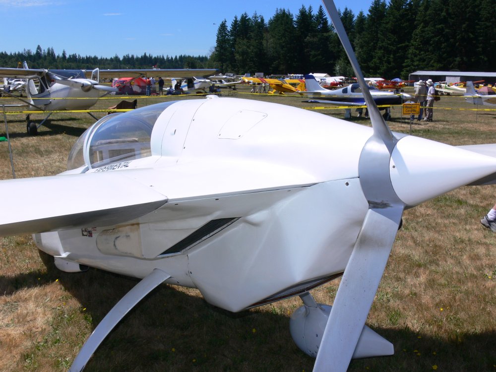
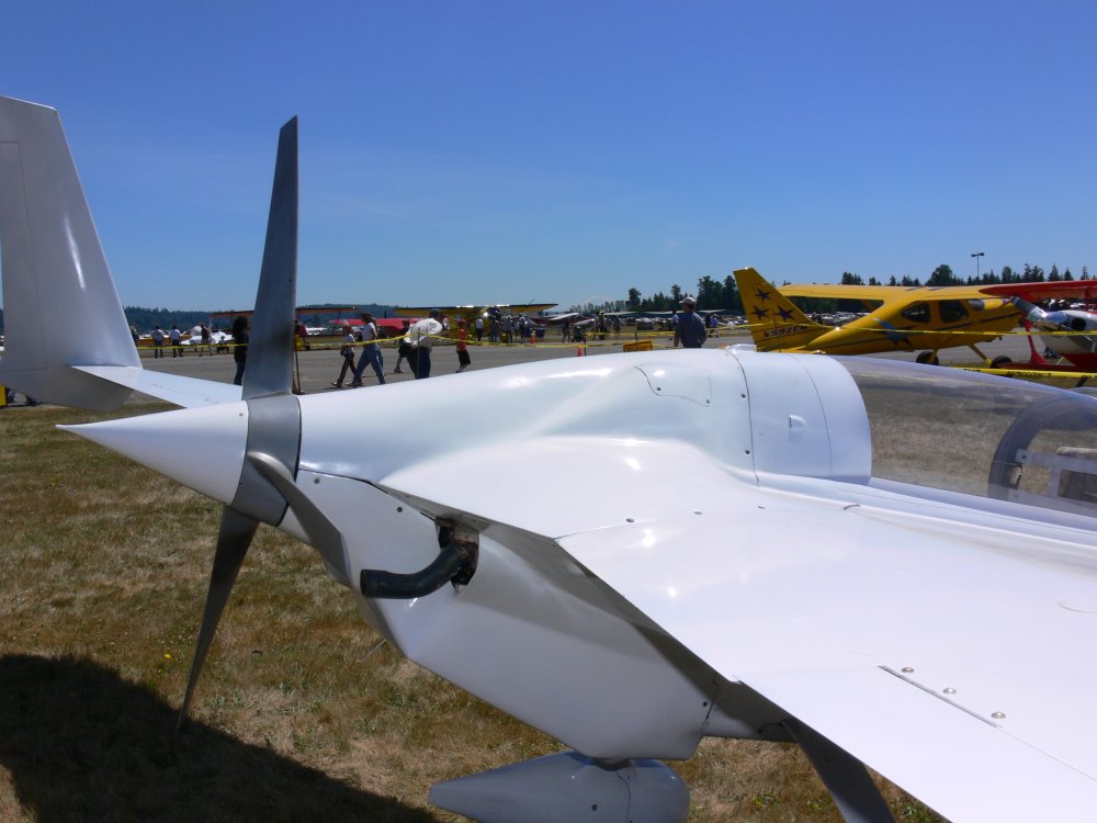
> I have a few pictures of the rad Buly cut in half.
> My guess it is 10 to 12 inches wide. Shows what can be done
> with a proper scoop and diffuser.
>
> BTW Scott how is the great experiment coming?
>
> Paul Lamar ...No rotor no motor.
>
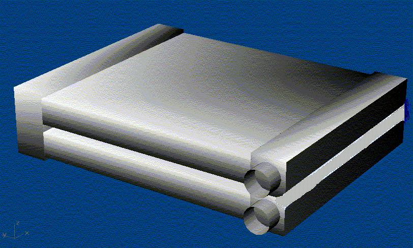
The reason I asked about Buly's radiators is that the core size I we
looked at fitting in front of my engine is (2)9x12x2.25", or 486 cubic
inches. Yet your book says 600 cubic inches are needed. I measured the
water radiator on my RX-8, and it looks like it has about 400 cubic
inches. The intake ducting is far from ideal. The car also has about
200 cubic inches of oil coolers, for a total of 600 cubic inches.
On the aerodynamic testing, I haven't been able to spend a lot of time
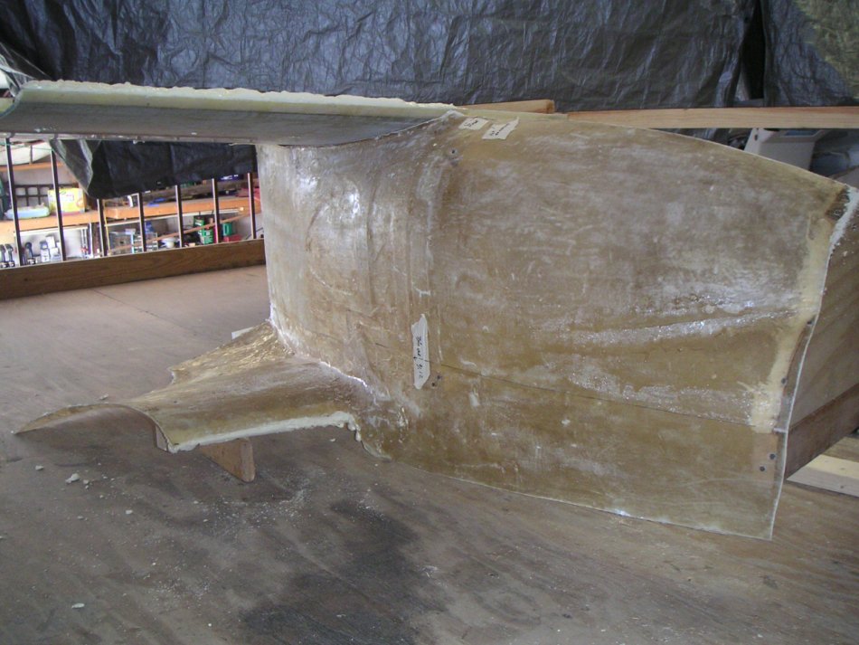
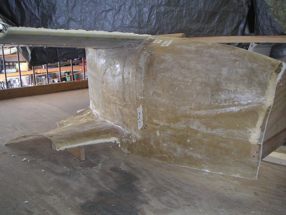
on my plane lately, but I have the mold/model of the side of the plane
done. I made an upper and lower surface for the upper wing root and
duct taped the leading edge smooth. I filled in the lower wing leading
edge area with foam and duct tape to make reasonable leading edge.
The water manometer is done. I've drilled holes thru the side of the
pylon in several locations so I can take readings from the back side. I
have the porous foam to cap the flexible tubing, but need to find a way
to seal the tubing end and foam from the back side, so I only get a
pressure reading from the hole. Maybe modeling clay or epoxy/micro?? I
didn't want to run the tubing on the outside due to the VG effect of so
many tubes.
What I have left to do is to fill and sand the outer surfaces smooth,
and figure out a way to mount the whole thing on top of my Explorer.
Should the wing stubs hang outside the edge of the vehicle to be in more
clear air? I don't want the vehicle airflow to give me false readings.
Scott Gettings
The 600 number is a conservative average assuming there will be flaws in design
and construction of the scoops and ducts.
The RX8 almost never generates 150 HP continuously.
It is more like 30 or 40 HP. The RX8 has an efficient heat exchanger.
It is probably 20 inches wide by 20 inches high and less than an inch thick.
Buly has an ideal P-51 style ram air scoop and diffuser with a wide open space behind the
the rad. My guess his core is a minimum of 20" by 12" by 2 inches which is 480 cubic inches.
If it is 14 inches wide the volume would be 560 cubic inches.
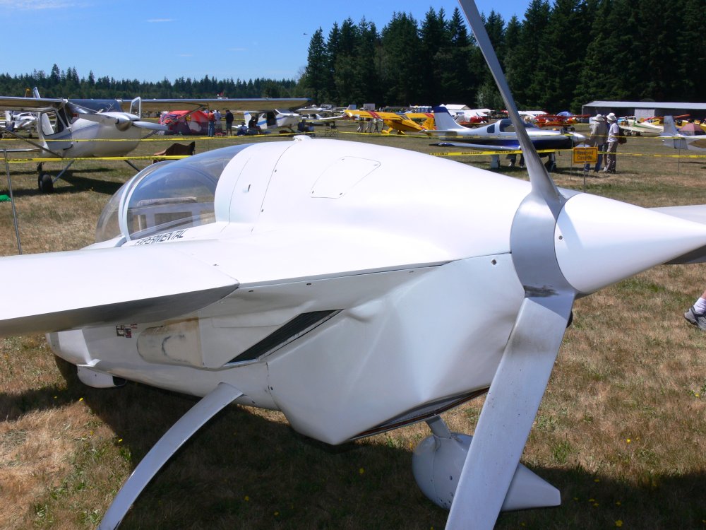
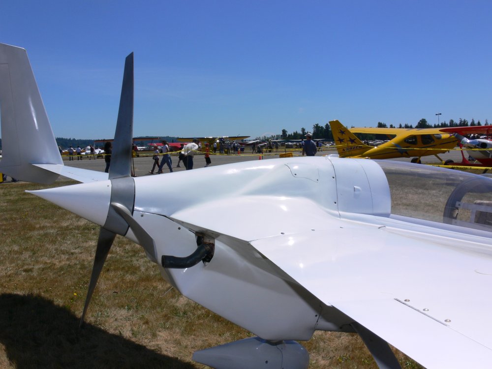
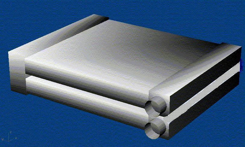
Perry Mick also has an ideal well sealed system. In fact his core is a super efficient
cross counter flow core. My guess it is 15" by 15" by 2" OA or 450 cubic inches.
The air exits into a very low pressure area behind the fuselage.
Although he does not use a ram air scoop the prop does a good job of sucking
the air out of the back side of his cross counter flow cores.
You could mount the test rig on top rotated 90 degrees with the
wing stubs pointing straight up. Move it out over the hood with two
longitudinal 10 foot long 4" by 4"s to get cleaner air. Take it out
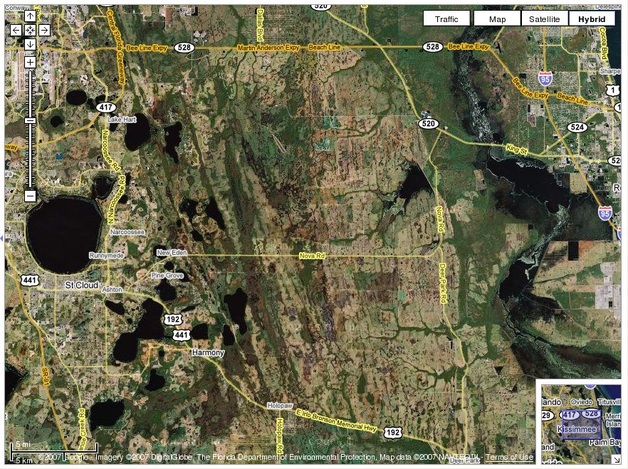
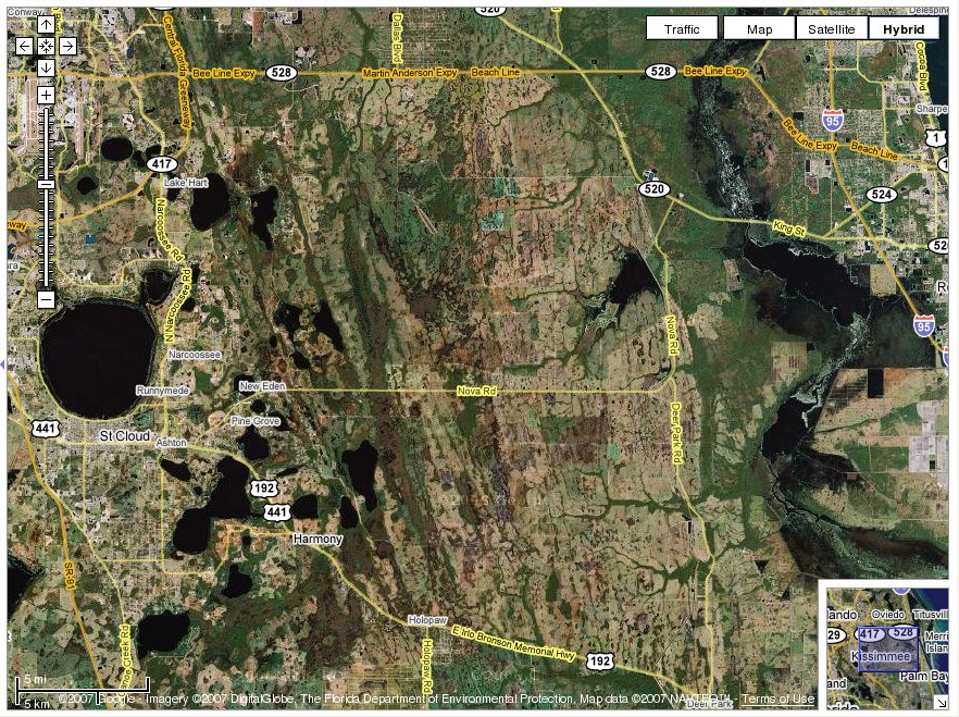
to the Florida out back to test it. Nova Road is a good one.
I have been down that one.
There will be a lot of lift on the rig due to pressure build up underneath
so run a good size nylon rope (3/4") around the middle of the 4-bys through the
upper part of the pax window and through the upper part of the driver window
as far forward as you can get it to insure you don't lose the rig. The lift on
the rig will be several hundred pounds at 80 MPH or so. You will have to get
in the back door of the Explorer :) I am also assuming the roof rack is strong.
Paul Lamar ...No rotor no motor.
The Rotary Engine NewsLetter. Powered by Linux.
ACRE NL web site.
http://www.rotaryeng.net
Copyright 1998-2006 All world wide rights reserved.